Errors in the I & Q quadrature phase relationship occur after the signals exit the AD9854 IC in the filters, unequal cable and PCB trace lengths and transformer differences, etc. System phase errors can not be corrected through programming changes of the AD9854. Its outputs are fixed in quadrature. Phase errors can be corrected by adjusting cable lengths from the AD9854 to the AD8346 evaluation board. Amplitude inequalities can be corrected using the AD9854’s 12-bit, independent sine and cosine (I & Q) digital amplitude multiplier stages.
Figure 8: Spectrum of a 200 MHz region of the AD8346 output centered around 1.05 GHz. The DDS “modulating” signals are fixed-frequency at 25 MHz from the AD9854. The LO is at 1.04 GHz (-8dBm) from a Rohde & Schwarz SMG signal generator.
In Fig. 8, a measured difference of -40 dB is indicated between the upper sideband (USB) and the lower sideband (LSB) amplitudes. The forty-dB power differential between upper and lower sidebands equates to a numerical power difference of about ten-thousand. This sideband suppression is indicative of approximately 1 degree of input-signal phase mismatch. Exchanging the sine and cosine DDS signals to the quadrature modulator will cause the favored sideband to be switched.
LO feedthrough amplitude (-36 dB) is greater than the diminished sideband in this setup. LO feedthrough level was not found to be affected by either the phase or amplitude of the DDS I & Q input signals and LO feedthrough could not be adjusted.
LO feedthrough can be made less significant by providing larger amplitude DDS modulating signals. This will increase the sideband amplitudes while LO feedthrough remains fixed. The AD8346 performance is specified at 1-volt p-p input levels. By increasing the input levels to 1-volt p-p from the 600mv level that was found to exist in this setup, a 4 dB improvement in signal-toLO feedthrough level can be obtained.
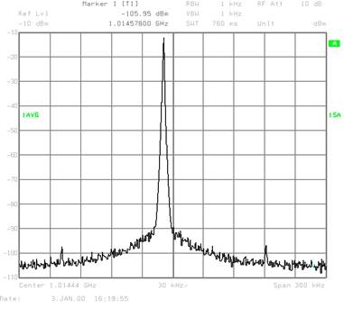
Figure 9: a close-in view of the 1.015 GHz lower sideband shown in Figure 8. Compare this upconverted signal to that of the PLL-multiplied signal in Figure 4.
The upconverted DDS signal from 25 MHz to >1GHz is shown in Figure 9. The signal’s phase noise is unaffected by the frequency transition and all other DDS attributes are preserved.
Quadrature modulation is a very promising method of DDS upconversion to UHF and microwave frequencies without losing any of the desirable attributes of DDS technology.
The AD8346 quadrature modulator simplifies the process. The AD9854 DDS, with its differential quadrature outputs, is a “natural” match. Add a quality LO, and UHF & microwave SSB output is readily achievable.
Since the AD9854 DDS has several modulation modes (AM, FM, FSK) this application supports a (nearly) complete AM, FM, FSK exciter at microwave output frequencies. With minor additional signal processing of the AM suppressed carrier I & Q DDS outputs, SSB voice or other amplitude modulation schemes are possible.
The typical 36dB sideband and LO rejection is directly useable in many applications and makes additional output filtering in other more demanding applications a much less formidable task. Adjusting the DDS I & Q signal phase relationship and amplitude balance can improve sideband suppression even further.
Use of the AD9854 DDS in this article by no means precludes the use other DDS IC’s such as the AD9850, AD9851 and the AD983x series. If two DDSs can be synchronized, then they can probably be programmed to achieve quadrature outputs using internal phase offset circuitry. The AD9854 Quadrature DDS was specifically designed to provide the appropriate output signals without the need for multiple DDSs to achieve the same function. Furthermore, the independently programmable I & Q output amplitudes make output matching a simple software routine.
The relative simplicity of quadrature DDS upconversion to over 2GHz as shown in this Technical Note should encourage designers to add this technique to their repertoire. This technique preserves every desirable DDS attribute at microwave frequencies yet drastically reduces the undesirable doublesideband product of mixer-upconversion.
Don’t be surprised when bumper-stickers proclaiming “Designers do it in Quadrature” show-up. It may be a prophecy that transposes expensive, exotic designs into affordable everyday commodities with excellent performance specifications.
Уважаемый посетитель!
Чтобы распечатать файл, скачайте его (в формате Word).
Ссылка на скачивание - внизу страницы.