CHEMCAD SCDS Distillation Column
CHEMCAD SUPERTEAM 2005
Experiment 300
ECH4404L
By:
Lakshmi Kastury
Mark Lescher
Introduction
This is a basic tutorial for the creation of an SCDS column using CHEMCAD software version 5.5.0. The initial conditions are specified in the objectives for the Distillation Experiment in the Unit Operations Laboratory Manual (ECH4404L).
Contents
Procedure
1. Starting CHEMCAD
1.1. Double click the CHEMCAD icon to run software.
1.2. To retrieve an existing file, click on “Open Job” in the “File” menu.
1.3. Select file, and click on “Open”.
1.4. To create new file click on “New Job” in the “File” menu.
1.5. Name new file, “SCDS column” and click “Save”.
2. Creating a Process Flow Diagram
2.1 The initial flow sheet will populate a selection table for various types of equipment. Equipment is listed in alphabetical order.
2.2 Moving curser through icons will allow for selection of the SCDS distillation column ( 7 down; 4 across)
2.3 Click on the SCDS Distillation column. This places the column on the flow sheet. Note: Right clicking on mouse will allow for additional selections of the flow arrangements for the SCDS column.
2.4 Now select the inlet (red) and outlet (blue) flow stream arrows.
2.5 Click the square labeled stream to connect the arrows to the inlet/outlets streams on column. An example process flow diagram is shown below:
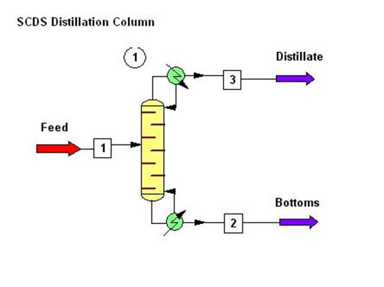
Figure 1 – SCDS Process Flow Diagram
3. Specification of Engineering Units
3.1 Click on “Format” and select “Engineering Units”.
3.2 Click on SI units and modify as specified below in the red square:
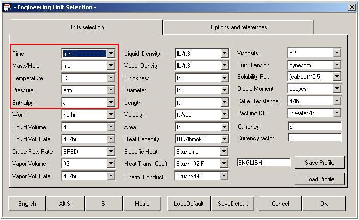
Figure 2
3.3 Now click on the “Options and references” tab and choose “Mole fractions” for the component flow.
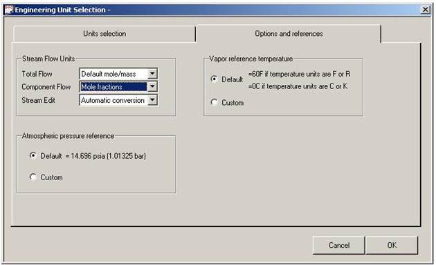
Figure 3
3.4 Click on “OK” to continue.
4. Specification of chemical components
4.1 Now click on the “Flow sheet” drop down menu and select “Simulation”.
4.2 Click on “Thermophysical” and select “Component List”.
4.3 Search for ethanol and list as the first component because it is more volatile. Click to add.
4.4 Search for n-propanol and click to add.
4.5 If initial search does not yield the desired chemical, click on next to continue the search. A sample diagram is given below.
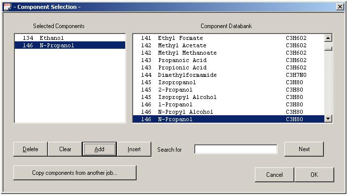
Figure 4
4.6 Once all components have been added, click “OK.”
4.7 The following box shown below will appear. Maintain the default specifications and click “OK.”
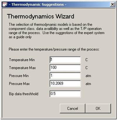
Figure 5
4.8 Next a box showing the K-value options will appear. Select the “Wilson” option as shown below and click “OK.”
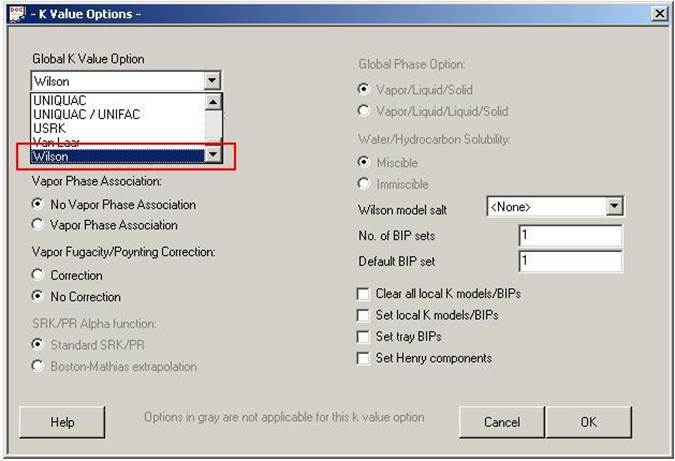
Figure 6
4.9 The next box that appears is shown below. Maintain the default settings and click “OK”.
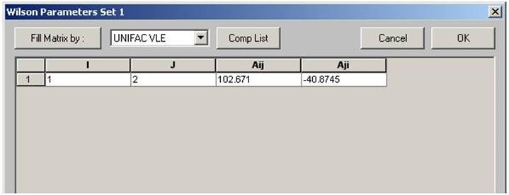
Figure 7
5. Entering feed stream compositions
5.1 Double click on stream number “1”.
5.2 For stream name enter “feed” and specify the following values for the temperature, pressure, total flow and mole fractions of ethanol and n-propanol.
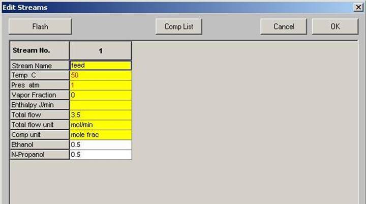
Figure 8
5.3 Click “Flash” button located in upper left corner.
5.4 Click “OK”.
6. Entering SCDS Column Specifications
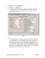
6.1 Double click on “SCDS column”.
6.2 A screen showing the specifications for the column will appear. Under the tab labeled “General” specify the values as outlined within the red box below. For Subcooled delta T, enter 32.2 C. For the number of stages enter 6, and for the feed stage for stream 1 enter 2.
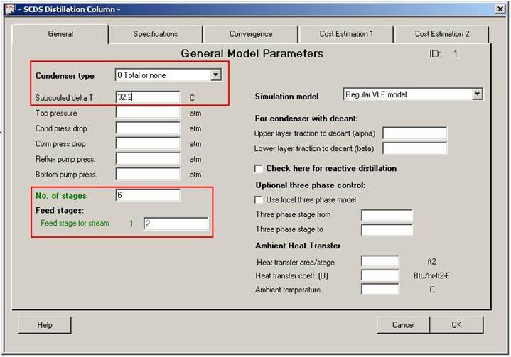
Figure 9
Note:
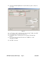
6.3 Under the tab labeled “Specifications” enter the following options, a diagram is given below.
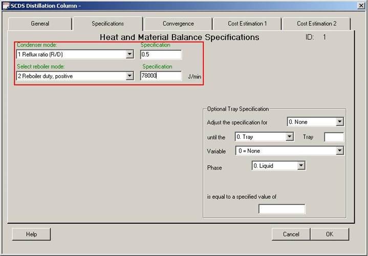
Figure 10
6.4 For “Condenser mode”, initiate drop down box and select “1 Reflux ratio (R/D)”.
6.5 Tab to specifications and enter desired ratio “0.5”.
6.6 For “Reboiler mode”, initiate drop down box and select “2 Reboiler duty positive”.
6.7 Tab to specifications and enter desired amount "78,000" J/min, which corresponds to 1300 W.
6.8 Click “OK” to continue.
7. Warnings
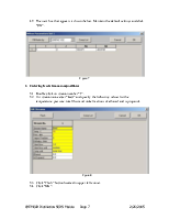
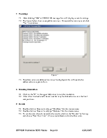
7.1 After clicking “OK” a CHEMCAD message box will display several warnings.
7.2 The figure below shows acceptable warnings. Disregard the warnings and click “Yes” to continue.
Уважаемый посетитель!
Чтобы распечатать файл, скачайте его (в формате Word).
Ссылка на скачивание - внизу страницы.