|
2.1 Basic Operations
2.1.1 Plugging/Unplugging Fiber Jumper
There is a large amount of SC optical interfaces on the handle bars of the boards in OptiX BWS 320G system. Under the condition of full configuration, each optical interface is plugged with fiber jumper with connector of SC/PC-FC/PC or SC/PC-SC/PC.
In case SC/PC fiber jumper should be unplugged, the special tool - fiber jumper extractor is required. If the extractor is unavailable on site, use a pair of sharp nose pliers instead. During the operation, be cautious to work with moderate force to avoid damaging fiber jumper connector.
When plugging the fiber jumper, align the connector of SC/PC fiber jumper with the optical interface of board, and plug the fiber jumper along with the guide path.
When unplugging the connector of FC/PC fiber jumper, first rotate the retaining screws in the anti-clockwise direction, then unplug the fiber jumper outward with a little force after the screws are loosened; when plugging the connector, be careful to align it with the guide path and plug it to the bottom, then rotate the screws in the clockwise direction.
2.1.2 Plugging/Unplugging and Replacing Board
There is a large amount of small pins in the positions which boards are plugged on the working subrack, be cautious when plugging/unplugging board to prevent pins from toppling, so as to avoid the great loss caused by system short-circuiting.
1. The correct method of unplugging a board
First loosen the screws at the up and down sides of handle bars on the board, then pull the levers at the up and down sides of handle bars outward simultaneously till the board is unplugged completely.
2. The correct method of plugging a board
(1) First make sure whether the slot which the board will be plugged in is correct.
(2) If there are some boards to be plugged, they should be plugged in the sequence from right to left or from left to right. In case there exist fake handle bars obstructing your view, the fake handle bars should be dismounted first and then replaced after the board is plugged.
(3) To plug a board, first push the board gently along the up and down sides guide paths to the bottom of this slot, and align the flute of up and down sides levers of handle bars on board with the up and down sides edges of subrack. Now the board is in float-plugged state.
(4) Make sure that the connector on board aligns with the socket on motherboard and the motherboard anti-misplug guide pin aligns with the board anti-misplug hole, then push the board handle bar with a little force till the board is basically plugged in the socket of motherboard. If you feel that board plugging is blocked, forced plugging is forbidden, and you should adjust the board position and then try again.
(5) When observing that the position of board connector completely matches with that of motherboard socket, press the up and down levers of handle bars inward till the board is plugged completely, then tighten the screws at both ends of board.
(6) Anti-electrostatic wrist should be worn whenever a board is touched.
& Note:
Float plugging a board means that the board is already in the slot that it should be plugged, but the board connector and motherboard socket are not connected yet; actually, the board is still in not-plugged state.
3. Replacing a board
When replacing a board, first make sure whether the board to be plugged and the unplugged board are of the same specific type and whether their operating characteristics are the same.
During equipment running, in case wavelength conversion board is damaged and should be replaced, please refer to the procedures of the following example, here we refer the TWF as example, the changing step of other wavelength conversion boards are the same :
& Note:
In OptiX BWS 320G system, if equipment is not configured fully, one or two TWF boards with different output optical signal wavelengths from those of the used TWF boards should be configured. For example, the TWF boards with wavelengths of 1~14 are used in a specific project, the TWF backup boards with output wavelengths of 15 and 16 should be configured, where, 1~16 wavelengths respectively refer to the required wavelengths of DWDM equipment which is in compliance with ITU-T G.692 specification. The transmitting and receiving module performances of different TWF boards are the same completely, while the only difference is that the output signal wavelengths are different.
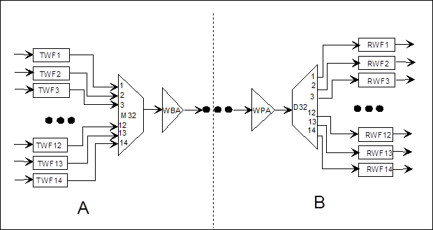
Figure 2-1 Unidirectional signal flow of main channel in a specific chain networking
In Figure 2-1, stations A and B are OTM equipment of chain networking, only the signal flow from station A to station B is illustrated in the figure. If TWF1 board should be replaced, but it is unavailable on site, use TWF16 board instead. The method is as follows:
(1) First replace the TWF1 board with TWF16 board in station A according to the correct method of plugging/unplugging a board.
(2) Unplug the fiber jumper at the first input port of M32 board in station A, then plug it in the 16th input port.
Уважаемый посетитель!
Чтобы распечатать файл, скачайте его (в формате Word).
Ссылка на скачивание - внизу страницы.