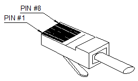
Figure 7-13 Network connector RJ45
2. Cable
The OptiX OSN 9500 uses straight through cable or cross-over network cable. Its structure is shown in Figure 7-14.
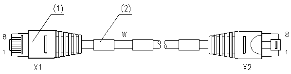
|
(1) Network interface connector |
(2) Label |
W: Category-5 twisted pair |
Figure 7-14 Network cable
3. Connections
There are two types of network cable, namely crossover cable and straight-through cable, available for connecting NM computer with gateway NE. The crossover cable is used to directly connect the gateway NE with the NM computer. The straight-through cable is used to connect the gateway NE with the NM computer through a HUB. They differ in the connection of internal cores.
Table 7-7 The connections of two types of network cable
|
Type of connection |
Applications |
Differences |
|
Cross-over network cable |
Connecting NM computer with gateway NE |
Internal core connection |
|
Straight through cable |
Connecting NM computer with gateway NE through HUB |
Table 7-8 The pin assignment of straight-through network cable
|
Head connector |
8-core category-5 twisted pair |
Tail connector |
|
Pin 1 |
White (orange) |
Pin 1 |
|
Pin 2 |
Orange |
Pin 2 |
|
Pin 3 |
White (green) |
Pin 3 |
|
Pin 4 |
Blue |
Pin 4 |
|
Pin 5 |
White (blue) |
Pin 5 |
|
Pin 6 |
Green |
Pin 6 |
|
Pin 7 |
White (brown) |
Pin 7 |
|
Pin 8 |
Brown |
Pin 8 |
The pin assignment of cross-over network cable is shown in Table 7-9.
Table 7-9 The pin assignment of cross-over connection
|
Head connector |
8-core category-5 twisted pair |
Tail connector |
|
Pin 1 |
White (orange) |
Pin 3 |
|
Pin 2 |
Orange |
Pin 6 |
|
Pin 3 |
White (green) |
Pin 1 |
|
Pin 4 |
Blue |
Pin 4 |
|
Pin 5 |
White (blue) |
Pin 5 |
|
Pin 6 |
Green |
Pin 2 |
|
Pin 7 |
White (brown) |
Pin 7 |
|
Pin 8 |
Brown |
Pin 8 |
4. Specifications
|
Type |
Category-5 twisted pair |
|
The number of cores |
8 |
|
Typical resistance |
100 ohm ±15% |
|
Attenuation (100 MHz) |
22 dB/100 m |
|
Color |
Grey |
|
Length |
5 m, 10 m and 20 m |
7.3.8 External Alarm Concatenation Cable
1. Structure
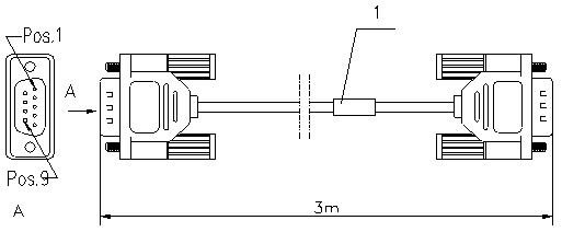
Figure 7-15 shows the structure of alarm concatenation cable.
|
1. Label |
Pos.1: the position of pin 1 |
|
Pos.9: the position of pin 9 |
Figure 7-15 The external view of alarm concatenation cable
2. Pin Assignment
Table 7-10 lists the pin assignment of alarm concatenation cable
Table 7-10 The pin assignment of alarm concatenation cable
|
Connector X |
Color of core |
Remarks |
|
1 |
Black |
Ground |
|
6 |
Black/white |
Major alarm |
|
3 |
Red |
Ground |
|
7 |
Red/white |
Emergency alarm |
|
4 |
Brown |
Ground |
|
8 |
Brown/white |
Auxiliary alarm 1 |
|
5 |
Orange |
Ground |
|
9 |
Orange/white |
Auxiliary alarm 2 |
3. Specifications
|
Type |
UL2464 |
|
The number cores |
4 P |
|
Color |
PANTONE WRAM GRAY 1U |
|
Length |
10 m |
7.3.9 Alarm Output Cable
1. Structure
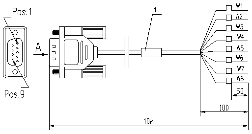
The structure of alarm output cable is shown in Figure 7-16.
|
1. Label |
Pos.1: the position of pin 1 |
|
Pos.9: the position of pin 9 |
W1–W8: core ID. |
Figure 7-16 The external view of alarm output cable
2. Core Assignment
Table 7-11 lists the core assignment of alarm output cable.
Уважаемый посетитель!
Чтобы распечатать файл, скачайте его (в формате Word).
Ссылка на скачивание - внизу страницы.