PROBLEM OF AUTOMATIZED INDUCTION MOTOR EXPERIMENTAL RESEARCH
Tey D., Shulgin Ev., Karlov B., Altinikov Iv.
Department of Design and Technology of Electronic and Computer Systems
Orel State Technical University
Naugorskoye Shosse 29, Orel, 302020, Russia
Tel: (4862) 41-98-79, Fax: (4862) 41-66-84, E-mail: teyd@mail.ru
Development of power electronics and microprocessor technology recently gave the opportunity to realize the induction motor (IM) control complex algorithm. It increases the practical application field of IM: crane drive, conveying drive, manipulator and robot drive etc. [1, 2, 3].
IM is described through complex nonlinear mathematical models, which have complicated precise solution. That’s why the simplified and linearized models are used in task of the IM investigation and projection [4]. This situation leads to the necessity of the experimental investigations with specific equipment. Also it needs to check the investigation result adequacy of the simplified models to the real system [5]. For this purpose the experimental plant and experimental research methods must create the operation mode and IM operating mode approached to the real ones. This demands the solution of the experimental research control tasks, which include: control of the automatized IM operating modes, control of the IM drives load, the control of the data acquisition and processing.
In the practical applications the IM drives operates with the loads, which creates the drag torque, can be the function of time and/or characteristics of rotation, i.e. of the velocity and acceleration. It can be divided in: function of the static moment depending on the angular velocity; squared relationship; function with falling part with low velocity and extensive starting torque; the gradational tern of the torque. The drag torque can be divided in active: which doesn’t change their sign while changing the direction of motion and reactive [6]. The task of the IM shaft load control, depending on the experimental mode can be divided into two types:
The control of the torque according to the mode M = f(n).
The control of the torque according to the mode M = f(t).
The experimental plant must provide the automatic data acquisition. These data must characterize the IM and IM control system operation. It is necessary to provide data acquisition, which characterize the condition of load. This data also help to determine and specify parameters of automatized IM-load system. Also data acquisition of the IM, IM control system and load conditions must occur simultaneously.
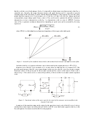
Problem of the IM torque control can be simplify if the DC motor with an independent excitation is used to create a load diagram. In this case DC motor can operate in following modes: a recuperative braking, a dynamic breaking or an opposite action mode [6]. Realization of the recuperative braking mode is sufficiently difficult due to the complicated experimental equipment, algorithms and small regulation range.
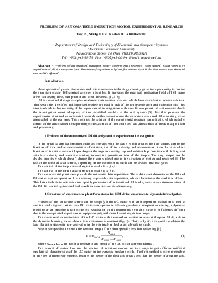
The mechanical characteristics of the DC motor with independent excitation cross at the point M=0, n=0 in the dynamic breaking mode when a load resistance is constant (fig. 1). That’s why it’s impossible to obtain the load characteristics with non-zero value in the point n=0 in the dynamic breaking mode.
Also it’s impossible to obtain the nominal torque if the shaft speed is less than following [6]:
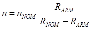 , (1)
, (1)
where RNOM, nNOM are nominal resistance and speed of the DC motor correspondently.
The control of motor flux and the control
of armature current are two ways to get different artificial mechanical
characteristics of the DC motor in the dynamic breaking mode. The first method
is more preferable in the view of the power expense, because the power of the
field coil greatly less than the power of armature coil. But this mode has some
disadvantages. Firstly, it’s impossible to obtain torque more than nominal when
flux is controlled only. Secondly, the torque decreases linearly with speed
decrease and it’s impossible to provide constant torque in the wide range of
speed. And the third disadvantage is a big response time (several orders
greater than the response time of an armature coil) of the flux coil that
limits the flux change speed and correspondently torque change speed. Hence,
control of flux can be used to generate the artificial mechanical
characteristics similar to characteristics on the fig. 2 or characteristics
with low value of ![]() .
Necessary value of flux to generate mechanical characteristics depending on
speed value can be calculated by following expression:
.
Necessary value of flux to generate mechanical characteristics depending on
speed value can be calculated by following expression:
Уважаемый посетитель!
Чтобы распечатать файл, скачайте его (в формате Word).
Ссылка на скачивание - внизу страницы.