 , (2)
, (2)
where ![]() is a beforehand known functional dependence of the torque on the
shaft speed.
is a beforehand known functional dependence of the torque on the
shaft speed.
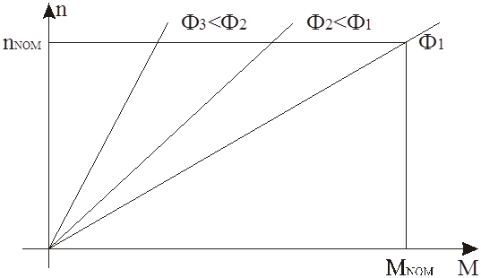
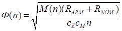
Figure 1 – Ensemble of the artificial characteristics with nominal load resistance and different value of flux
And after it the flux coil regulator
reference value is determined by the magnetization curve ![]() .
.
Response time of the DC motor armature coil is several orders less than the flux coil response time. This provides speed increase of the DC motor torque change. In the same time, the DC motor flux remains constant. Functional scheme of the power part for the armature current and flux control in the dynamic break mode is shown in fig. 2. This scheme allows to realize the possibility of the reversible for armature current regulation mode.
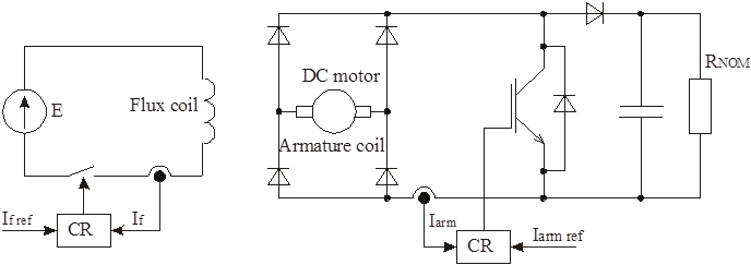
Figure 2 – Functional scheme of the power part for the control of the armature current and flux in the dynamic break mode
Expansion of the regulation range can be realized in the opposition circuit mode of the DC motor. It allows creating the nominal torque even in the point n=0. In this mode DC motor shaft rotates opposite relatively to the flux and equation of armature circuit has the following equation:
![]() .
(3),
.
(3),
where U – voltage of the external voltage source for the armature circuit; Е – induced motor voltage.
Induced DC motor voltage tends to the zero value when shaft speed is close to zero. In this moment armature current is determined by the voltage of the external voltage source, which produces torque with opposite direction relatively to the DC motor shaft.
Load diagram creation algorithm in the opposition circuit mode doesn’t defer from the load diagram creation algorithm in the dynamic break mode. Value of external voltage source must compensate voltage drop in the brush collector of the DC motor and voltage drop of the armature resistance. The drop on the armature resistance is determined by the value of the armature current for nominal torque producing in the point n=0.
Figure 3 – Functional scheme of the power part for the control of the armature current and flux in the opposition circuit mode
The automatization of the experimental investigations is achieved through utilization of microprocessor-based control system on the low level and utilization of the personal computer (PC) on the high level. Database of the various experiment scenario contains in the PC of the automated workbench. Initialization of all plant modules passes before starting the experiment. It includes tuning of the measurement system and assembling the experimental algorithm. Microprocessor control system must have the significant computing power to provide the big quantity of calculations, which are necessary for the realization of the load control algorithms and data acquisition. The developed control system is based on DSP and realizes the pulse control of the armature current and the DC motor flux through the IM shaft velocity rotation information, which is received from the encoder (fig. 4). Besides the control tasks, the control system provides the data acquisition, indication and information about the states of the experimental plant transmission in the PC. PC initiates the data acquisition, which is realized by the data acquisition board. The functional diagram of the experimental plant for the automatized IM investigation, which is realized in the laboratory of the department “Design and Technology of Electronic System”, is show on the fig. 4.
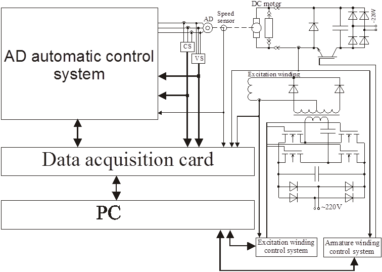
Figure 4 – Functional scheme of the experimental plant for automatized IM dynamics research
[1] I.Ya. Braslavsky, Z.Sh. Ishmatov, Yu.V. Plotnikov, Power and resource-saving technology based on a controlled induction motor, Electrotehnika, 2004, vol. 9. p.33-39.
[2] A. Kolpakov, Electric drive development perspective, Silovaya electronica, vol. 1, p. 46-47, 2004
[3] N.F. Ilinsky, Controlled electric drive development perspective, Electrichestvo, vol. 2, p.2-7, 2003
[4] V.V. Pankratov, E.A. Zima, Mathematical simulation of the induction motors and motors with dual source, Electrotehnika, vol. 9, p. 19-24, 2003
[5] M.V. Andrianov, Ed.Ev. Malishev, R.V. Rodionov, Experimental research of frequency-controlled induction motor, Electrotehnika, vol. 5, p.37-41, 2005
[6] V.I. Kluchev, Theory of electric drive, Moscow: Energoatomizdat, 2001
Уважаемый посетитель!
Чтобы распечатать файл, скачайте его (в формате Word).
Ссылка на скачивание - внизу страницы.