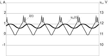
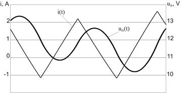
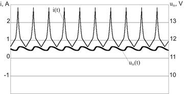
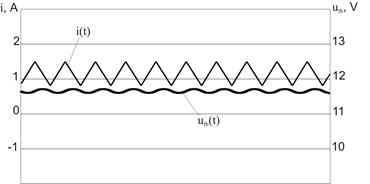
Distinction in behavior of the models with both linear and nonlinear inductors is evidently illustrated by the time diagrams of the currents and voltages (Fig. 4). At R3=18 Ω and a=25 for the nonlinear inductor model the subharmonic mode with the period 2 (П2.1) exists (Fig. 4, a) while for linear inductor model the chaotic mode is realized (Fig. 4, b). Absence of the modes with high periods at rather high load resistance (R3>15 Ω) leads to smaller pulsations of the voltages and currents (Imax=1,7A, DU=0,36 V for the nonlinear inductor model and Imax=2,63 A, DU=3,1 V for the linear one). On the other hand, at the modes with the identical periods much greater currents are observed for the nonlinear inductor model at rather small pulsations of the voltage. It is caused by the inductor saturation to which almost vertical segments on the time diagrams correspond. On figures 4 c, d currents and voltages diagrams of both models for the mode with the period 1 (П1.1) are presented at load resistance of 10 Ω and a=5.
a) b)
c) d)
Fig. 4 - Diagrams of currents for models with nonlinear (a, c) and linear (b, d) inductors
At the specified values of the buck converter parameters the maximal inductor current for the linear inductor model makes 1,49 A, DU=0,08 V (Fig. 4, d) while for the nonlinear inductor model the maximal current is equal to 2,84 A at the saturation of an inductor, DU=0,19 V (Fig. 4, c).
4. CONCLUSION
The researches carried out in the paper have revealed significant difference of dynamics of the DC-DC buck converter models with the linear and nonlinear inductors. Though inductor saturation leads to reduction of the synchronous mode existence domain, the areas of existence of subharmonic modes with big periods which are dangerous from the practical viewpoint are reduced. It is also necessary to note that the inductor saturation at low load resistance leads to growth of an amplitude of a current through the switch elements that negatively affects efficiency and reliability of the converter.
5. REFERENCES
[1] R. Severns, G. Bloom DC-DC buck converters for systems of secondary power supplies. - Moscow: Energoatomizdat, 1988.
[2] V.S. Moin "Stabilized transistor converters". - Moscow: Energoatomizdat, 1986.
[3] "Sources of secondary power supplies" / S.S.Bukreev, V.A.Golovatsky, G.N.Guljakovich, etc.; Under edition of Yu.I.Konev. - Moscow: Radio i svyaz, 1983.
[4] Yu.V. Kolokolov, S.L. Koschinsky, A.P. Sholonik "Dynamics of a buck converter operating in discontinuous conduction mode". - Electrichestvo, 2003, №9.
[5] G.A. Belov "Research of oscillations in a pulse voltage stabilizer near to border of stability". - Electrichestvo, 1990, 9.
[6] G. Yuan, S. Banerjee, E. Ott, and J.A. Yorke, « Border-Collision Bifurcations in the Buck Converter », IEEE Transactions on Circuits and Systems-I: Fundamental Theory and Аpplications, vol. 45, no. 7, July 1998.
[7] M. Di Bernardo, E. Fossas, G. Olivar, F. Vasca, " Secondary Bifurcations And High Periodic Orbits In Voltage Controlled Buck Converter ", International Journal Of Bifurcation And Chaos, Vol. 7, No. 12 (1997).
[8] E. Hairer, S. Norsett, G. Wanner "Solving ordinary differential equations". - Moscow: Mir, 1990.
[9] A.M. Bamdas, Yu.A. Savinovsky "Inductors of an alternating current of the radio-electronic equipment (coils with steel)".- Moscow: Sovetskoe radio, 1969.
Уважаемый посетитель!
Чтобы распечатать файл, скачайте его (в формате Word).
Ссылка на скачивание - внизу страницы.