DYNAMICS OF THE DC-DC BUCK CONVERTER WITH NONLINEAR INDUCTOR
Alexander S. Kuzmin, Grigory V. Kudinov
Department of Design and Technology of Electronic and Computing Systems, State Technical University of Orel (OrelSTU), 29 Naugorskoye shosse, Orel, 302020, Russia
Тел.: +7(4862) 419550, E-mail: ask-alex-k@yandex.ru, ggrigori@yandex.ru
Abstract – The mathematical model of the DC-DC buck converter considering nonlinearity of the inductor is resulted. The basic features of converter's dynamics caused by nonlinearity of the inductor are presented.
1. INTRODUCTION
One of characteristic representatives of essentially nonlinear automatic control systems is the DC-DC buck converter with pulse-width modulation (PWM) [1-3]. Existence of undesirable dynamic modes (subharmonic, quasiperiodic and chaotic) in similar systems is the conventional fact [4-7].
Significant part of weight and dimensions of the modern DC-DC buck converter makes an inductor. The aspiration to reduce weight and dimensions of an inductor can lead to saturation of the inductor core magnetic material during operation of a DC-DC buck converter. This is especially fairly for a DC-DC buck converter functioning in a wide variety of load resistance. The mathematical models of a power circuit used in the known publications devoted to the research of the DC-DC buck converter dynamics [4-7] don't consider the nonlinearity of an inductor magnetization curve and, therefore, nonlinear dependence of the magnetic flux through an inductor on its current. It reduces the adequacy of the previously received results.
In the paper the mathematical model of a DC-DC buck converter in the form of a system of the differential equations with the discontinuous right side is presented considering the nonlinearity of an inductor; the research of the DC-DC buck converter dynamics is carried out with use of the presented model.
2. MATHEMATICAL MODEL OF A DC-DC BUCK CONVERTER
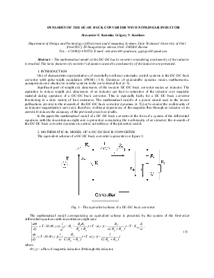
The equivalent scheme of a DC-DC buck converter is presented on figure 1.
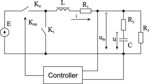
Fig. 1 - The equivalent scheme of a DC-DC buck converter
The mathematical model corresponding an equivalent scheme is presented by the system of the first-order differential equations with discontinuous right side:
 (1)
(1)
where
Ф (g) – a flux of magnetic induction B through the inductor;
u (g) – a capacitor voltage;
γ є [0,1] – a relative time for pulse-width modulation (PWM) period;
Т – a value of the PWM period;
H (Ф (γ)) – a function expressing dependence of a magnetic field intensity on the flux through the inductor core;
l – a length of a magnetic centerline of the inductor core;
w – a number of the inductor coil turns;
The regulator realizes single-cycle PWM with modulation of the back front with the proportional control mode. The control is carried out on output voltage (ufb).
Value of pulse function KF0 is calculated according to the following algorithm
 (2)
(2)
where γ0 – a moment of switching corresponding the transition of К0 switch to non-conducting mode and К1 switch - to conducting one.
Value ![]() is calculated as the least root of the commutation
equation
is calculated as the least root of the commutation
equation
 , (3)
, (3)
where
 - a vector of a system state variables;
![]() – a proportional gain;
– a proportional gain;
![]() – a gain of an output voltage divider;
– a gain of an output voltage divider;
Uref – a reference voltage;
U0 - amplitude of a sawtooth voltage;
 - row vector, establishing conformity
between vector
- row vector, establishing conformity
between vector  and the regulator input voltage(ufb).
The presented mathematical model of the DC-DC buck converter differs from known [1, 4-7] ones by the use of the magnetic flux Ф as one of the system state variables instead of an inductor current i(γ). Other essential distinction of the presented model is its nonlinearity on structure constancy sections of the right side of system (1) (КF0=const), caused by function H(B).
Уважаемый посетитель!
Чтобы распечатать файл, скачайте его (в формате Word).
Ссылка на скачивание - внизу страницы.