3. DYNAMICS OF A DC-DC BUCK CONVERTER
Results of the research of
dynamics of a DC-DC buck converter obtained with use of the model (1-3) are
presented in the form of two-parametrical diagram of dynamic modes (Fig. 2, a)
for following parameters of model: R1 = 0,1 Ω; R2 = 0,1 Ω; C = 10-5
F; E = 24 V; ![]() = 1; U0 = 3 V; Uref = 12 V;
f = 105 Hz with variation of load resistance R3 from 2 up to 50 Ω
and variation of the regulator proportional gain from 2 up to 30. The diagram
on figure 2, a is obtained using the nonlinear inductor. The inductor has
following parameters: standard size К10х5х5 (length of a magnetic centerline l=23,6
mm); number of coil turns w=10. The material of inductor core is ГМ515В.
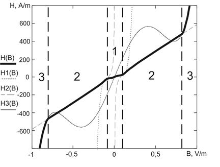
Dependence H(B) was approximated by a curve consisting of three sections
without taking into account the hysteresis (Fig. 3). On section 1 function
= 1; U0 = 3 V; Uref = 12 V;
f = 105 Hz with variation of load resistance R3 from 2 up to 50 Ω
and variation of the regulator proportional gain from 2 up to 30. The diagram
on figure 2, a is obtained using the nonlinear inductor. The inductor has
following parameters: standard size К10х5х5 (length of a magnetic centerline l=23,6
mm); number of coil turns w=10. The material of inductor core is ГМ515В.
Dependence H(B) was approximated by a curve consisting of three sections
without taking into account the hysteresis (Fig. 3). On section 1 function ![]() was used; on sections 2 – function
was used; on sections 2 – function ![]() ; on sections 3 –
; on sections 3 – ![]() . Approximation was chosen according to the recommendations
in [9]. Maximal mean square deviation from the magnetization curve in ordinate
axis for the chosen material on the third section is 2,635 A/m. The inductance
of an equivalent linear inductor L at the average current 0,7 A for the period
(R3=18 Ω) is 10-4 H. To plot the diagram for model with
linear inductance (Fig. 2, b) linear dependence H (B) was used at which
the value of L was 10-4 H.
. Approximation was chosen according to the recommendations
in [9]. Maximal mean square deviation from the magnetization curve in ordinate
axis for the chosen material on the third section is 2,635 A/m. The inductance
of an equivalent linear inductor L at the average current 0,7 A for the period
(R3=18 Ω) is 10-4 H. To plot the diagram for model with
linear inductance (Fig. 2, b) linear dependence H (B) was used at which
the value of L was 10-4 H.
The solution of system (1) was
obtained on the structure constancy sections by integration using the fifth-order
Dorman-Prince method [8]. The value of γ0 was estimated as a
crosspoint of linear approximation of the commutation function graph ![]() and an abscissa axis. Approximation was obtained by
splitting PWM period Т into 100 pieces and calculating the value
of commutation function at the beginning of each piece.
and an abscissa axis. Approximation was obtained by
splitting PWM period Т into 100 pieces and calculating the value
of commutation function at the beginning of each piece.
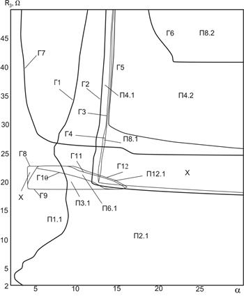
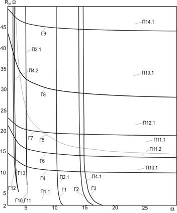
a) b)
Fig. 2 - Two-parametrical diagram of dynamic modes for a DC-DC buck converter with nonlinear (a) and linear (b) inductor
On the diagrams (Fig. 2) the following symbols are used: subharmonic modes are designated by symbol П with two indexes divided by a point. The first index represents the rate of a subharmonic mode period to PWM period, the second one introduces distinction of subharmonic modes with the identical period. The boundaries of mode existence domains are designated by symbol Г and figure identifying the number of borders.
![]() On each of the diagrams there is the cascade
of bifurcations of period doubling that is typical for a DC-DC buck converter
[4]. Thus the sizes of subharmonic mode existence domains essentially differ.
In particular, at R3>20 Ω for the nonlinear inductor
model displacement of the borders Г1, Г2, Г3 of the modes П1.1, П2.1, П4.1
aside reduction of a-parameter is observed.
In the field of the diagram at R3<20 Ω the
displacement of the borders Г2 and Г3 of the modes with the periods, greater
than 2 is observed to the right down to the border of the examined range of a-values and further. Absence of modes with
periods greater than 2 in the field of low resistance (R3<17 Ω) is also the
essential difference of dynamics of the nonlinear inductor model. Other
difference is the practically full absence of modes with high (more than 8)
periods in examined area of the parameters’ space (Fig. 2, a). Only the small
area П12.1 was found out. At the same time the periodic modes П11.1, П11.2,
П12.1, П13.1, П14.1 occupy significant area on the diagram for the linear
inductor model. Also the sizes of chaotic mode existence domains essentially
differ. For the linear inductor model at a>15 in the resistance range R3<30
Ω the chaotic mode exists. Under similar conditions for the nonlinear inductor
model such area is found out basically only in the R3 resistance range
from 18 up to 30 Ω. The size of chaotic oscillations existence domain was
considerably reduced as a result of occurrence of the modes П4.2 and П8.2 (the borders
Г5 and Г6 accordingly) in the top right part of the diagram. The specified mode
П4.2 exists practically in all examined range of a-values and resistance R3>25 Ω
parallel to modes П1.1, П2.1, П4.1, П8.1 and to the mode of chaotic oscillations
(the border Г7). Besides, in the field of R3 resistance change
from 18 Ω up to 23 Ω and a-parameter
from 4 up to 17 modes with the periods multiple to 3 - П3.1, П6.1, П12.1
existing in parallel with П1.1, П2.1, П4.1, П8.1 were found out, while such
modes are absent in the linear inductor model.
On each of the diagrams there is the cascade
of bifurcations of period doubling that is typical for a DC-DC buck converter
[4]. Thus the sizes of subharmonic mode existence domains essentially differ.
In particular, at R3>20 Ω for the nonlinear inductor
model displacement of the borders Г1, Г2, Г3 of the modes П1.1, П2.1, П4.1
aside reduction of a-parameter is observed.
In the field of the diagram at R3<20 Ω the
displacement of the borders Г2 and Г3 of the modes with the periods, greater
than 2 is observed to the right down to the border of the examined range of a-values and further. Absence of modes with
periods greater than 2 in the field of low resistance (R3<17 Ω) is also the
essential difference of dynamics of the nonlinear inductor model. Other
difference is the practically full absence of modes with high (more than 8)
periods in examined area of the parameters’ space (Fig. 2, a). Only the small
area П12.1 was found out. At the same time the periodic modes П11.1, П11.2,
П12.1, П13.1, П14.1 occupy significant area on the diagram for the linear
inductor model. Also the sizes of chaotic mode existence domains essentially
differ. For the linear inductor model at a>15 in the resistance range R3<30
Ω the chaotic mode exists. Under similar conditions for the nonlinear inductor
model such area is found out basically only in the R3 resistance range
from 18 up to 30 Ω. The size of chaotic oscillations existence domain was
considerably reduced as a result of occurrence of the modes П4.2 and П8.2 (the borders
Г5 and Г6 accordingly) in the top right part of the diagram. The specified mode
П4.2 exists practically in all examined range of a-values and resistance R3>25 Ω
parallel to modes П1.1, П2.1, П4.1, П8.1 and to the mode of chaotic oscillations
(the border Г7). Besides, in the field of R3 resistance change
from 18 Ω up to 23 Ω and a-parameter
from 4 up to 17 modes with the periods multiple to 3 - П3.1, П6.1, П12.1
existing in parallel with П1.1, П2.1, П4.1, П8.1 were found out, while such
modes are absent in the linear inductor model.
Уважаемый посетитель!
Чтобы распечатать файл, скачайте его (в формате Word).
Ссылка на скачивание - внизу страницы.