Testing and Adjusting 784C and 785C Off-Highway Truck/Tractors Power Train
|
Media Number --07 |
Publication Date -01/03/2004 |
Date Updated -08/03/2004 |
|
|
SMCS - 3000; 3100; 4000
|
|
|
|
View Image
|
|
|
|
|
|
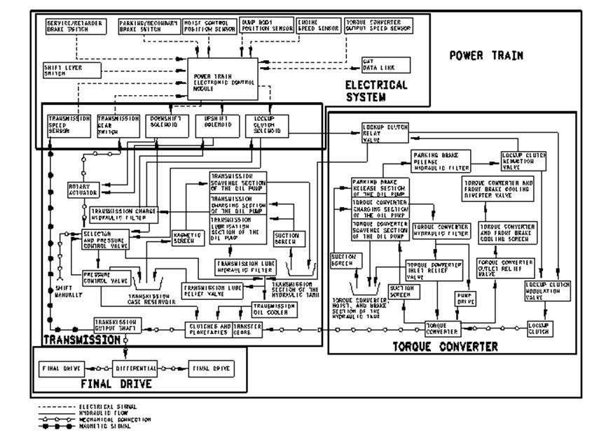
Illustration 1 |
g00498556 |
The power train consists of four basic systems. The following systems are the four basic systems:
The four basic systems are connected by an electrical connection, a hydraulic connection, a magnetic connection, or a mechanical connection.
The operation of the power train begins at the Power Train Electronic Control Module (Power Train ECM). The Power Train ECM receives the information of the selected operating speed from the shift lever switch in the electrical system. The Power Train ECM uses the information from the switches and the sensors in the electrical system to control the hydraulic system of the torque converter and transmission. This is done by energizing the appropriate solenoids.
The torque converter has a lockup clutch for direct drive and a one-way clutch for torque converter drive. In torque converter drive, the torque converter drives the transmission hydraulically. The torque converter is fastened directly to the flywheel of the engine.
The lockup clutch solenoid is activated by the Power Train ECM when direct drive is required. When the lockup clutch solenoid is activated, the lockup clutch is hydraulically engaged. The rotating housing of the torque converter is mechanically connected to the output shaft of the torque converter. The drive shaft mechanically connects the torque converter to the transfer gears. The transfer gears are fastened directly to the transmission.
The upshift solenoid and the downshift solenoid hydraulically activate the rotary actuator of the transmission. Movement of the rotary actuator mechanically selects the position of the rotary selector spool. The flow through the rotary selector spool hydraulically activates the correct valves in the pressure control valve. These valves engage the correct transmission clutches. This mechanically connects the transmission input shaft to the output shaft and to the differential. The transmission will not drive the output shaft unless there is power flow through the torque converter. The power flow can be hydraulic or mechanical.
After the transmission and the torque converter are connected, power is supplied from the engine to the differential through the torque converter, the transfer gears, and the transmission. The rear axles mechanically connect the differential to the final drives. When the transmission is in the correct speed position, the mechanical movement of the rotary selector spool causes the transmission gear switch to electrically signal the Power Train ECM that the shift is complete. With the rotation of the transmission output shaft, the transmission speed sensor electrically transmits the output speed of the transmission to the Power Train ECM.
This function restricts coasting into NEUTRAL from high speeds. This restriction extends the life of the transmission. The transmission speed sensor measures the rotation of the gear teeth on a gear that is fastened to the transmission output shaft. The Power Train ECM uses the input signal from the transmission speed sensor to determine the ground speed. If the measured speed is greater than 8 km/h (5 mph), the transmission will not shift into NEUTRAL.
Note: The operator can bypass the restriction against neutral coasting. However, if the ground speed is greater than 16 km/h (10 mph) and the transmission is in NEUTRAL, the event will be recorded in the Vital Information Management System (VIMS).
If the transmission is in any forward speed and the transmission control is moved to REVERSE, the transmission will immediately make a shift to NEUTRAL. When the ground speed decreases to approximately 5 km/h (3 mph), the transmission will make a shift into REVERSE from the NEUTRAL position.
Уважаемый посетитель!
Чтобы распечатать файл, скачайте его (в формате Word).
Ссылка на скачивание - внизу страницы.