Troubleshooting C27 and C32 Engines for 773F and 777F Off-Highway Truck/Tractors and for the 775F Quarry Truck
|
Media Number --05 |
Publication Date -01/12/2008 |
Date Updated -04/12/2008 |
|
|
SMCS -
System Operation Description:
Use this procedure for the following conditions:
Use this procedure for the following diagnostic codes:
Perform this procedure under conditions that are identical to the conditions that exist when the problem occurs. Typically, problems with the injector solenoid occur when the engine is warmed up and/or when the engine is under vibration (heavy loads).
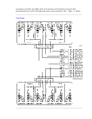
These engines have Electronic Unit Injectors (EUI) that are mechanically actuated and electronically controlled. The Engine Control Module (ECM) sends a high voltage signal to each injector solenoid. The signal is sent with the proper injection duration and injection timing for the current engine load and speed. The injector solenoid is mounted on top of the fuel injector body.
If an open circuit condition is detected in the solenoid circuit, a diagnostic code is generated. The ECM will continue to try to fire the injector. If a short circuit condition is detected, a diagnostic code is generated. The ECM will disable the solenoid circuit. The ECM will periodically try to fire the injector. If the short circuit condition remains, this sequence of events will be repeated until the problem is corrected.
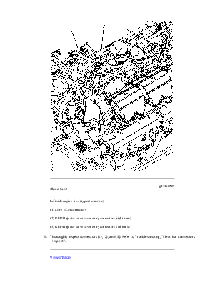
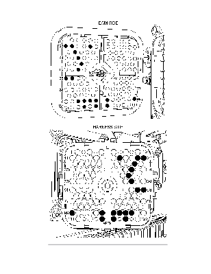
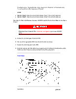
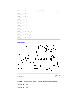
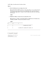
Note: Refer to Illustration 1. Two injector solenoids share a supply wire. For this reason, an open circuit or a short circuit in a supply wire could cause diagnostic codes for two injector solenoids.
When an injector is replaced, new injector trim files must be programmed into the ECM. If the ECM is replaced, all injector trim files must be programmed into the new ECM. Refer to Troubleshooting, "Injector Trim File" for more information.
The Caterpillar Electronic Technician (ET) includes the following tests that aid in troubleshooting the injector solenoids:
"Cylinder Cutout Test"
The "Cylinder Cutout Test" is used on an engine in order to determine the individual cylinder performance while the engine is running. As one or more cylinders are cut out during the test, the "Cylinder Cutout Test" uses "Fuel Position" in order to evaluate the performance of the cylinders that are cut out. As the different cylinders are cut out, a comparison of the change in "Fuel Position" is used to identify cylinders that are weak or misfiring. One reason for a cylinder that is weak or misfiring is an injector that is malfunctioning.
The "Cylinder Cutout Test" can be used to isolate a malfunctioning injector in order to avoid replacement of injectors that are in good condition.
During the test, when a cylinder is cut out, an increase in "Fuel Position" will be noticed for the remaining cylinders. This increase in "Fuel Position" represents an increase in the amount of fuel that must be delivered by the remaining cylinders in order to maintain the desired engine speed.
Уважаемый посетитель!
Чтобы распечатать файл, скачайте его (в формате Word).
Ссылка на скачивание - внизу страницы.