Test Step 4. Perform the "Injector Solenoid Test"
Expected Result:
All cylinders indicate "OK" on Cat ET.
Results:
Repair: The problem appears to be resolved. There may be an intermittent problem in the harness. The problem may have been caused by a poor electrical connection in a connector.If the codes continue to be logged, refer to Troubleshooting, "Electrical Connectors - Inspect".If the engine is misfiring or if the engine has low power, refer to Troubleshooting, "Engine Misfires, Runs Rough or Is Unstable" or Troubleshooting, "Low Power/Poor or No Response to Throttle".
STOP
Test Step 5. Check the Harness between the ECM and the Valve Cover Base for an Open Circuit
|
|
|
Electrical shock hazard. The electronic unit injector system uses 90-120 volts. |
|
|
|
|
|
|
View Image
|
|
|
|
|
|
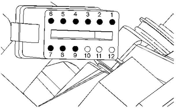
Illustration 6 |
g01203187 |
|
P4 terminals that are associated with the injector solenoids (harness side of connector) (P4-1) Injector 12 return (P4-2) Injector 10 return (P4-3) Injector 8 return (P4-4) Injector 6 return (P4-5) Injector 4 return (P4-6) Injector 2 return (P4-7) Injectors 10 & 12 supply (P4-8) Injectors 6 & 8 supply (P4-9) Injectors 2 & 4 supply |
|
|
|
|
|
View Image
|
|
|
|
|
|
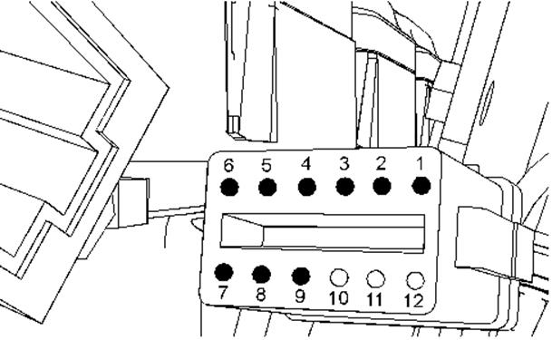
Illustration 7 |
g01161304 |
|
P3 terminals that are associated with the injector solenoids (harness side of connector) (P3-1) Injector 1 return (P3-2) Injector 3 return (P3-3) Injector 5 return (P3-4) Injector 7 return (P3-5) Injector 9 return (P3-6) Injector 11 return (P3-7) Injectors 1 & 3 supply (P3-8) Injectors 5 & 7 supply (P3-9) Injectors 9 & 11 supply |
|
Уважаемый посетитель!
Чтобы распечатать файл, скачайте его (в формате Word).
Ссылка на скачивание - внизу страницы.