




Troubleshooting C27 and C32 Engines for 773F and 777F Off-Highway Truck/Tractors and for the 775F Quarry Truck
|
Media Number --05 |
Publication Date -01/12/2008 |
Date Updated -04/12/2008 |
|
|
SMCS -
System Operation Description:
Use this procedure to troubleshoot any suspect problems with the compression brake solenoids.
Use this procedure for the following diagnostic codes:
Note: A switch input to the brake Electronic Control Module (ECM) sets the status of the compression brake. The status is off or automatic. Software for the brake ECM controls the level of braking. The levels of braking are low, medium and high. The brake ECM requests the engine ECM in order to actuate the compression brake solenoids. The request is sent over the Cat data link.
Perform this procedure under conditions that are identical to the conditions that exist when the problem occurs. Typically, problems with the compression brake solenoids occur when the engine is warmed up and/or when the engine is under vibration (heavy loads).
"Compression Brake Solenoid Test"
The "Compression Brake Solenoid Test" is a diagnostic test that is available on Caterpillar Electronic Technician (ET). Use the "Compression Brake Solenoid Test" to assist in troubleshooting problems in the circuit for the compression brake. The engine Electronic Control Module (ECM) will only detect shorts in the circuit for the compression brake when the test is active. "Current high" diagnostic codes (short circuits) will be logged once the test has been deactivated. The ECM will only detect opens in the circuit for the compression brake when the test is not active. The test must be activated and then deactivated before the ECM will detect an open circuit. "Current low" diagnostic codes (open circuits) will be active once the test has been deactivated.
Note: The engine speed must be zero before the "Compression Brake Solenoid Test" will function.
|
|
|
|
View Image
|
|
|
|
|
|
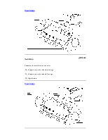
Illustration 1 |
g01199118 |
|
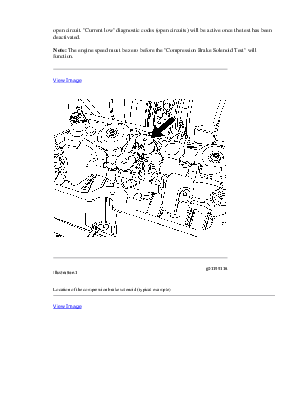
Location of the compression brake solenoid (typical example) |
|
|
|
|
|
View Image
|
|
|
|
|
|
Illustration 2 |
g01268745 |
|
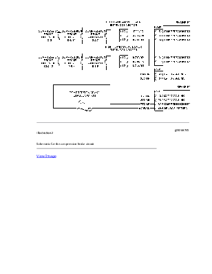
Schematic for the compression brake circuit |
|
|
|
|
|
View Image
|
|
|
|
|
|
Illustration 3 |
g01270061 |
|
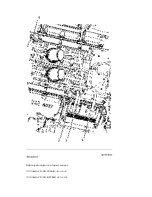
Right top side engine view (typical example) (1) Connector for the left bank valve cover (2) Connector for the right bank valve cover (3) J2/P2 ECM connectors (4) J1/P1 ECM connectors |
|
Test Step 1. Inspect the Electrical Connectors and the Wiring
|
|
|
Electrical shock hazard. The electronic unit injector system uses 90-120 volts. |
|
|
|
|
|
|
View Image
|
|
|
|
|
|
Illustration 4 |
g01141312 |
|
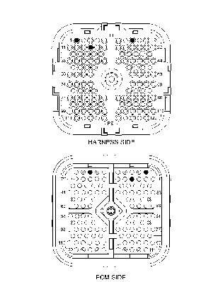
P2Connector for the engine ECM (P2-1) Compression brake solenoid low/high (P2-8) Compression brake solenoid med/high (P2-14) Digital return |
|
|
|
|
|
View Image
|
|
|
|
|
|
Illustration 5 |
g01270811 |
|
P1Connector for the Engine ECM (P1-8) Cat data link + (P1-9) Cat data link − |
|
|
|
|
|
View Image
|
|
|
|
|
|
Illustration 6 |
g01195659 |
|
Connector for the left bank valve cover (10) Compression brake solenoid med/high (11) Compression brake solenoid low/high (12) Digital return |
|
Уважаемый посетитель!
Чтобы распечатать файл, скачайте его (в формате Word).
Ссылка на скачивание - внизу страницы.