Ministry of Education and Science of Ukraine
Zhukovskiy National Aerospace University
“Kharkov Aviation Institute”
Department 402
Analysis of magnetic field configuration during the deposition of coating on parts made of magnetically soft materials.
Explanatory note to the special part of the diploma project
Executor:
Student of group 461P I.O. Oleksandrov
Scientific advisor:
Associate Professor of dep. 402 L.V.Litovchenko
Language advisor:
Associate Professor of dep. 706 L.I.Volchanskaya
Kharkov 2009
CONTENTS
1 The aim of magnetic system in the magnetron sputtering system (MSS) 3
1.1 Main magnetic system of the MSS. 3
1.2. Compensating magnetic system of the MSS. 5
2. Usage of the ANSYS 6.0 software for designing of compensating magnetic system. 6
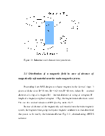
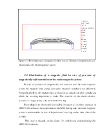
2.1 Distribution of a magnetic field in case of absence of magnetically soft material near the main magnetic system. 8
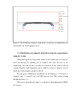
2.2 Distribution of a magnetic field in case of presence of magnetically soft material near the main magnetic system. 9
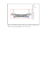
2.3 Distribution of a magnetic field while using the compensatory magnetic system. 10
3. Design of the main and auxiliary magnetic systems. 12
CONCLUSION.. 13
1 The aim of magnetic system in the magnetron sputtering
system (MSS)
1.1 Main magnetic system of the MSS
The magnetic system which is one of the main structural elements of magnetron system, should shape a field of the given configuration and value with minimum dispersion above the surface of a target for the purpose of an effective magnetic trap for electrons. Investigations on magnetic fields simulation have allowed to determine the most appropriate types of magnetic system from the point of view of simplicity and capability of obtaining of the demanded geometry and value of a magnetic field.
The magnetic system showed on fig. 4.7, is enough simple enough and ensures effective localization of plasma in case of a deposition on a material which is not giving in to magnetization. In this construction it is possible to use composite ring magnetic units.
For magnetron system it is necessary to ensure the value of a magnetic field induction B over the area of sputtering which should be equal the rate of 0,1 T. As the field is nonuniform, value B makes 0,7 of the magnetic induction value at a magnet edge: B=0,7·Bmax. Thus, Bmax=0,1/0,7=0,14 T.
To ensure the guaranteed value of magnetic induction above the working area of the MSS, we shall increase the value of a magnetic induction in 1,2 times. Finally we will gain the induction with desired value: B=0,17 Т.
The main characteristic of the magnet is the value of the residual induction Br - this is the maximum value of induction which material possesses after magnetization up to saturation . At a partial demagnetization of a magnet we will gain the desired value of induction.
Thus, while selecting the magnetic medium we should accomplish the following demand:
|
B<Br |
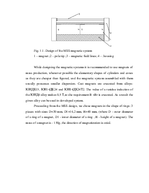
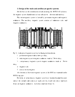
Fig. 1.1. Design of the MSS magnetic system
1 – magnet ;2 – pole tip ;3 – magnetic field lines; 4 – .housing
While designing the magnetic systems it is recommended to use magnets of mass production, whenever possible the elementary shapes of cylinders and cones as they are cheaper than figured, and the magnetic system assembled with them usually possesses smaller dispersion. Cast magnets are executed from alloys: ЮНДК15, ЮН14ДК24 and ЮН14ДК24Т2. The value of a residue induction of the ЮНД4 alloy makes 0,5 Т,so she requirement B <Br is executed. As a result the given alloy can be used in developed system.
Proceeding from the MSS design, we chose magnets in the shape of rings: 3 pieces with sizes D=30 mm, D1=16,2 mm, H=40 mm, (where D - outer diameter of a ring of a magnet, D1 - inner diameter of a ring , H - height of a magnet). The mass of a magnet is - 150g, the direction of magnetization is axial.
1.2. Compensating magnetic system of the MSS
For compensation of the magnetic properties of a material of the shock absorber cylinder the auxiliary magnetic system is used. The auxiliary system consists of eight coils, located outside of the cylinder, opposite to each section of the MSS The compensating system allows to localize a direction of magnetic lines parallel to the sprayed surface.
As the coating is deposited on the magnetically soft steel 30ХГСНА-ВД there is a problem of localisation of magnetic lines from permanent magnets near the sputtering surface of the cathode-target.
For the solution of this problem by means of ANSYS 6.0 software it is possible to simulate the behaviour of magnetic lines in a gap between the cathode-target and the surface on which the coating is deposited.
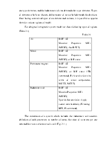
Properties of the materials participating in magnetic field formation should be defined for simulation of the field behavior. Such properies should be described for: permanent magnets, electromagnets, magnetic conducters and the cylinder of the shock absorber .
The selection of materials for magnetic conducters is defined by following demands: large peak magnetic permeability and large value of the induction of saturation. Proceeding from the termed demands, taking into accout the system working conditions we select a magnetic conducter material - magnetic-soft precision alloy 79НМ.
2. Usage of the ANSYS 6.0 software for designing of compensating magnetic system.
Procedure of accomplishment of the static magnetic analysis consists of five main steps:
1. Making the physical environment.
2. Building-up and meshing of models and assignment of physical properties to each region within model.
3. Application of boundary conditions.
4. Solution deriving.
5. Analysis of results.
In definition of a physical environment for the analysis, the ANSYS preprocessor (PREP7) is entered and the imitating mathematical model of a physical problem is created. It is carried out by following actions:
Уважаемый посетитель!
Чтобы распечатать файл, скачайте его (в формате Word).
Ссылка на скачивание - внизу страницы.