GRABOWSKI et al.: DEVELOPMENT OF A HIGH-CURRENT LOW-INDUCTANCE CROWBAR SWITCH 1913
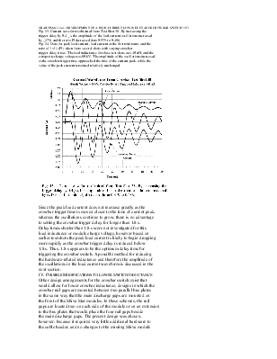
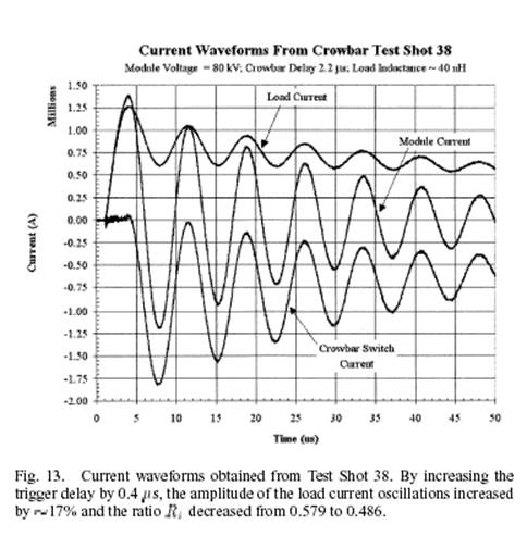
Fig. 13. Current waveforms obtained from Test Shot 38. By increasing the
trigger delay by 0.4 _s, the amplitude of the load current oscillations increased
by _17% and the ratio R decreased from 0.579 to 0.486.
Fig. 14. Data for peak load current, load current at the first minimum, and the
ratio of I =I (=R ) taken from several shots with varying crowbar
trigger delay times. The load inductance for these test shots was 40 nH, and the
composite charge voltagewas 80 kV. The amplitude of the oscillations increased
as the crowbar trigger time approached the time of the current peak, while the
value of the peak current remained relatively unchanged.
Since the peak load current does not increase greatly as the
crowbar trigger time is moved closer to the time of current peak,
whereas the oscillations continue to grow, there is no advantage
to setting the crowbar trigger delay for longer than 1.8 s.
Delay times shorter than 1.8 s were not investigated for this
load inductance or module charge voltage, however based on
earlier test shots the peak load current is likely to begin dropping
more rapidly as the crowbar trigger delay is reduced below
1.8 s. Thus, 1.8 s appears to be the optimum delay time for
triggering the crowbar switch. A possible method for reducing
the hardware-related inductance and therefore the amplitude of
the oscillations in the load current waveform is discussed in the
next section.
IV. POSSIBLEMODIFICATIONS TO LOWER SWITCH INDUCTANCE
Other design arrangements for the crowbar switch exist that
would allow for lower crowbar inductance, designs in which the
crowbar rail gaps are mounted between two parallel bus plates
in the same way that the main discharge gaps are mounted on
the front of the Shiva Star modules. In these schemes, the rail
gaps are located two on each side of the module or on an extension
to the bus plates that would place the four rail gaps beside
the main discharge gaps. The present design was chosen,
however, because it required very little additional hardware to
the cable header, and no changes to the existing Shiva module
hardware (bus plates) were needed. Analysis and experiments
may show that the field-reversed configuration is stable enough
such that the oscillations in the crowbarred reverse discharge
current (reverse magnetic field) will not significantly affect its
formation and lifetime. However, if the current oscillations are
found to have an adverse affect on the FRC, examination of the
present crowbar switch design shows that there are some relatively
minor changes can be made to reduce the crowbar switch
inductance and thereby reduce the amplitude of the current oscillations.
A cross-sectional diagram of the crowbar switch configuration
with the proposed changes indicated is presented in
Fig. 15. At present the crowbar rail gaps are approximately
9/16 in. above the bottom edge of the support brackets holding
them; if the rail gaps are moved down until their bottom edge
is even with the support brackets, and if both the lower face
of the support brackets and the rail gaps are moved down by
an additional 0.5 in., as shown in the figure, then calculations
show that the inductance of the crowbar switch can be reduced
by approximately 4.47 nH.
To determine what kind of effect reducing the switch inductance
by this amount would have on the load current waveform,
some simulations of the crowbar test circuit were performed
again using Micro-Cap. Fig. 16 shows the first 18 19 s of
the load current waveform from Test Shot 37 along with the
calculated load current waveform provided by Micro-Cap. Assuming
a switch inductance of 10.1 nH, fairly good agreement
is obtained between the Micro-Cap calculation and the experimental
result, at least until s. When the total
crowbar switch inductance is reduced by 4.47 nH, the third trace
in Fig. 16 is obtained. This trace has a slightly lower peak current,
1.18 MA, however the value of the current at the first
minimum has risen to 800 kA, resulting in a ratio of 0.68.
(Recall that for Test Shot 37 is 0.579.) As indicated in Fig. 15,
the only hardware components that would need to be modified
in order to obtain this improvement are the angle brackets supporting
the crowbar rail gaps above the cable header. Thus, this
improvement could be made at relatively little cost and down
time.
V. SUMMARY AND EVALUATION OF PERFORMANCE
The crowbar tests were performed with charge voltages of
up to 80 kV on the Shiva capacitor bank module, during which
currents of up to 1.25 MA were crowbarred. No evidence of
flashover in the crowbar or load cable headers was observed
when the headers were adequately filled with SF . In order to
achieve the desired load current (theta coil current) of 1.5 MA,
however, the charge voltage will have to be increased to slightly
higher values of 100 kV. As long as an adequate filling of
Уважаемый посетитель!
Чтобы распечатать файл, скачайте его (в формате Word).
Ссылка на скачивание - внизу страницы.