Pipe Simulator
Problem Statement:

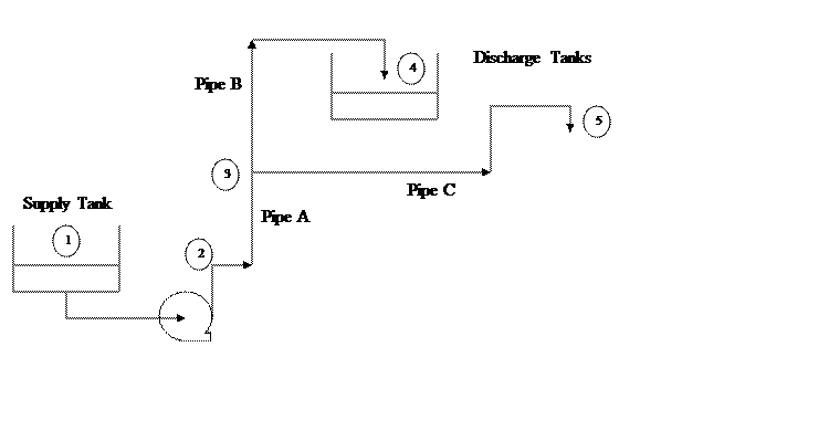
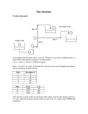
In the piping network shown above, water at 77F and 14.7 psi is fed at 2509 lbmol/h to a pump whose characteristic equation is as shown below:
![]()
Pipes A, B and C are made of schedule 40, commercial steel and the pipeline parameters and elevations are as shown below:
|
Node |
Elevation, ft |
|
1 |
0 |
|
2 |
0 |
|
3 |
25 |
|
4 |
80 |
|
5 |
60 |
|
Pipe |
D, in |
L, ft |
|
A |
3.068 |
80 |
|
B |
2.067 |
300 |
|
C |
2.067 |
500 |
If the pressure at inlets of the two discharge tanks (nodes 4 and 5 in the diagram above) is 14.7 psi, report the flowrates and pressures at each of the five nodes using CHEMCAD simulation.
Procedure:
Step 1: Creating the flow sheet
Step 2: Entering the components and formatting engineering units
Step 3: Entering the feed stream composition
Step 4: Entering the pump specs
Step 5: Entering the pipe simulator specs
Step 6: Entering the node specs
Step 7: Running the simulation and retrieving the results
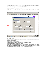
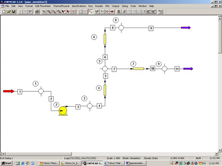
The supply tank is just a source of water for the pump and can be ignored for the purposes of the simulation. Select and click feed, pump, pipe simulators (three) and product(two) icons on the workspace. Also click on node (icon in the 10th row and third column). This node icon needs to be present before and after each pump and pipe when simulating a piping network. So we need five nodes for our flowsheet consisting of three pipes. For the purposes of this simulation, we can ignore the discharge tanks and just use product icons in their place. Connect all the icons using stream as shown in the following figure. Click once on the S/G icon on the menu bar to switch the simulation mode from Edit Simulation to Run Simulation.
Go to the Thermophysical on the menu bar and click on Components List. water from the CHEMCAD components list and add it to the component list. Go to the Format menu and click on Engineering Units and select the desired units for such properties as temperature, pressure etc. Use SI option to convert all units at the same time. Click OK to continue.
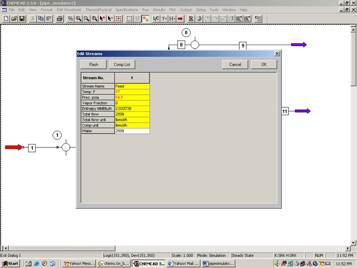
Step 3: Entering the feed stream composition
Double click on the feed stream and enter the feed information (temperature=77 F, pressure=14.7 psi, water flow rate=2509 lbmol/h) given in the problem statement. Click once on Flash to get the feed stream enthalpy and vapor fraction in feed at the feed conditions.
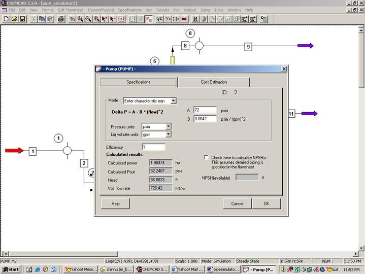
Step 4: Entering Pump Specs
Double click on Pump.
Under the specifications page, select Enter characteristic eqn for mode. Select psia for Pressure units and gpm for liq. vol. rate units. Enter 72 for A and 0.0042 for B. Efficiency can be left blank as that information is not provided in the problem statement. (the default value for efficiency is 100%). Click on OK to continue.
Step 5: Entering the pipe simulator specs
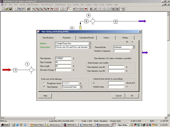
Double click on the first pipe simulator (Pipe A according to problem statement and unit operation 4 in my CHEMCAD simulation).
Specifications:
Method: Select option 2, Single phase flow
Sizing option: Select option 5, Given size, Pin and Pout, calc flow rate
Pipe Diameter: Convert the given diameter for Pipe A into feet using F6 key on the keyboard and enter the value in feet in this box (0.256 ft)
Pipe Schedule: Enter 40
Pipe Length: Enter 80 ft
Elevation change: Leave this blank, CHEMCAD calculates this automatically based on the specs given to nodes.
Roughness factor: Leave this blank
Pipe Material: Select commercial steel
Click on OK to continue.
Similarly, complete step 5 for pipes B and C.
Step 6: Entering node specs
There are five nodes on our flow sheet, specifications of each one of the five are different and dependent on the two unit ops they are connected to. Usually, when the node is in the middle of the flow sheet, Flow set by unit op is preferred as the flowrate spec. When the node is in the beginning or end of the flow line, one can select Free inlet stream and Free outlet stream respectively. If the input node flowrate of the stream is the same as that of the output from the previous unit op, Use current stream rate is preferred. For more information on how each of these options specifically function, click on help. Provide 0.001 psi and 100 psi as the minimum and maximum bounds for pressure as and when applicable. Providing the minimum and maximum bounds will speed up the calculations. However, these are optional inputs and can be left blank.
First node (Unit Op 1 on my flow sheet):
Double click on node. Choose variable pressure for mode. There is no elevation for this node according to the problem statement.
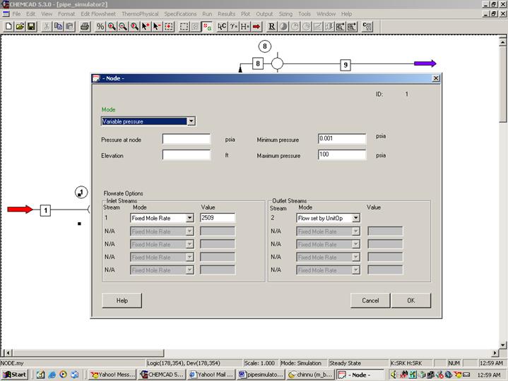
Flowrate Options:
Inlet Stream: Stream 1
Select Fixed mole rate option and enter the value 2059 lbmol/hr as stated in the problem
Outlet Stream: Stream 2
Select Flow set by UnitOp option
Click OK to continue. (Ignore the no pressure estimation warning)
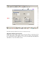
Second node (Unit Op 3 on my flow sheet):
Double click on node. Choose variable pressure for mode. There is no elevation for this node according to the problem statement. Under flowrate options, select Flow set by unit op for both node inlet and node outlet as shown in the following figure.
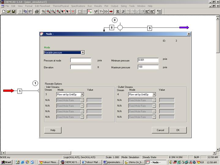
Click OK to continue. (Ignore the no pressure estimation warning)
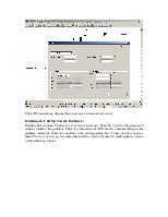
Third node (Unit Op 5 on my flow sheet):
Double click on node. Choose variable pressure for mode. There is an elevation of 25 ft for this node according to the problem statement. Enter this number in the corresponding box. Under flowrate options, select Flow set by unit op for both node inlet and the two node outlets as shown in the following figure.
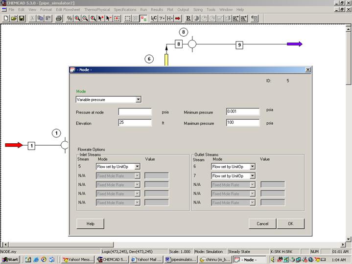
Click OK to continue. (Ignore the no pressure estimation warning)
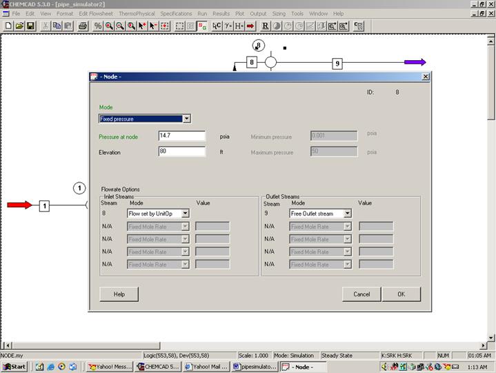
Fourth node (Unit Op 8 on my flowsheet):
Double click on node. Choose fixed pressure for mode. Enter 14.7 psi for the pressure at node as stated in the problem. There is an elevation of 80 ft for this node according to the problem statement. Enter this number in the corresponding box. Under flowrate options, select Flow set by unit op for node inlet and Free Outlet Stream for node outlet as shown in the following figure.
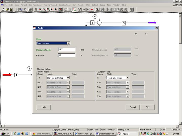
Fifth node (Unit Op 9 on my flowsheet):
Double click on node. Choose fixed pressure for mode. Enter 14.7 psi for the pressure at node as stated in the problem. There is an elevation of 60 ft for this node according to the problem statement. Enter this number in the corresponding box. Under flowrate options, select Flow set by unit op for node inlet and Free Outlet Stream for node outlet as shown in the following figure.
Step 7: Running the simulation and retrieving the results
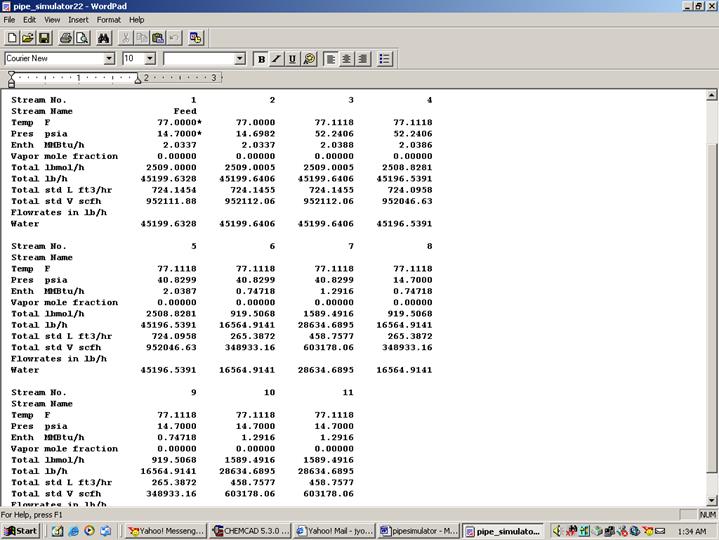
Now the simulation is ready to be run. Click once on R to run the simulation. Alternatively, one can run the simulation by clicking on Run on the menu bar and selecting Run all. The status of the simulation can be found at the bottom left hand corner of the screen. The message, Run Finished appears in this place if the run is successfully completed. The stream properties can be retrieved by clicking Results, selecting Stream compositions and then All streams. The results obtained are shown below.
Уважаемый посетитель!
Чтобы распечатать файл, скачайте его (в формате Word).
Ссылка на скачивание - внизу страницы.