
For PC-DMIS 3.0 and above
Wilcox Associates, Inc.
http://www.wilcoxassoc.com
Temperature Compensation Setup............................................................................................... 1
Contents........................................................................................................................................................... 3
Temperature Compensation Setup............................................................................................................... 4
Available Input Parameters....................................................................................................................... 4
Sensor Numbers boxes................................................................................................................................ 4
Material Coefficient boxes........................................................................................................................... 4
Current Temp boxes.................................................................................................................................... 5
Prev Temp boxes......................................................................................................................................... 5
Ref Temp boxes.......................................................................................................................................... 5
High Threshld boxes.................................................................................................................................... 5
Low Threshld boxes.................................................................................................................................... 6
Origin boxes................................................................................................................................................ 6
Show Temperatures in Celsius..................................................................................................................... 6
Temperature Compensation Enabled........................................................................................................... 6
Compensation Method................................................................................................................................. 6
Time Remaining........................................................................................................................................... 7
Delay Before Reading Part........................................................................................................................... 7
Reset to Defaults.......................................................................................................................................... 8
Get Current Temps....................................................................................................................................... 8
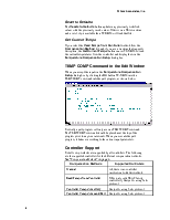
TEMP COMP Command in the Edit Window............................................................................................ 8
Controller Support...................................................................................................................................... 8
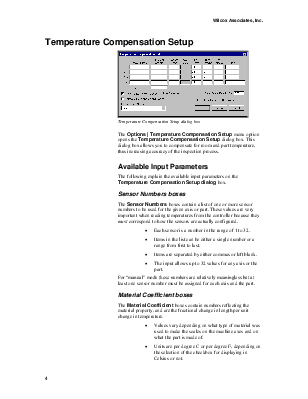
{bmct tempcomp.shg}
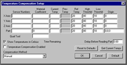
Temperature Compensation Setup dialog box
The Options | Temperature Compensation Setup menu option opens the Temperature Compensation Setup dialog box. This dialog box allows you to compensate for room and part temperature, thus increasing accuracy of the inspection process.
The following explain the available input parameters on the Temperature Compensation Setup dialog box.
The Sensor Numbers boxes contain a list of one or more sensor numbers to be used for the given axis or part. These values are very important when reading temperatures from the controller because they must correspond to how the sensors are actually configured.
· Each sensor is a number in the range of 1 to 32.
· Items in the list can be either a single number or a range from first to last.
· Items are separated by either commas or left blank.
· The input allows up to 32 values for any axis or the part.
For “manual” mode these numbers are relatively meaningless but at least one sensor number must be assigned for each axis and the part.
The Material Coefficient boxes contain numbers reflecting the material property, and are the fractional change in length per unit change in temperature.
· Values vary depending on what type of material was used to make the scales on the machine axes and on what the part is made of.
· Units are per degree C or per degree F, depending on the selection of the checkbox for displaying in Celsius or not.
· This can be thought of as meters/meter/degree C or inches/inch/degree F but since the length in both the numerator and denominator are in the same units they divide out.
Example: A scale with a coefficient of 11.5 microns/meter/degree C becomes 0.0000115 meters/meter/degree C or just 0.0000115/degree C.
Qual Tool
This box allows you to specify the material coefficient for the probe qualification tool separately from the part.
The Current Temp boxes contain the current temperatures in the appropriate units. You can either type these or read them in from the controller depending on the type of machine available and the selected options.
The Previous Temp boxes always contain the previously read temperatures. If no temperatures were previously read in, these values are either zero or left blank.
The Ref Temp boxes contain the reference temperature from which temperature compensation adjustments need to be applied.
· The amount of correction to be applied is based on multiplying the material coefficient by the difference between the current and reference temperatures. Amount of Correction = Material Coefficient x (Current Temp – Reference Temp)
· If the current temperature is the same as the reference temperature the net effect is that no thermal compensation adjustment is applied.
· The value in these boxes is almost always 20 degrees C, or the Fahrenheit equivalent.
The High Threshld boxes contain an upper limit (in the appropriate units) on the current temperature above which no further thermal compensation will be applied. PC-DMIS doesn’t prodcue any warning or error message.
Example: With a reference temp of 20 degrees C, a current temp of 35 degrees C and a high threshold of 30 degrees C the amount of correction actually applied would be based on a difference of (30 – 20) instead of (35 – 20) because the current temperature exceeded the upper limit.
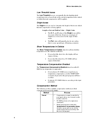
The Low Threshld boxes is conceptually like the high threshold except it provides a lower limit on the current temperature below which no further thermal compensation will be applied.
The Origin boxes are used to determine the length of the item to which thermal compensation is being applied.
Length = Current Position Value – Origin Value
· The X, Y, and Z values of the Origin boxes will be zero most of the time. However, some types of machines do not use zero for the origin of their scales.
· The Part value will typically also be zero unless there is some special type of fixturing constraint.
The Show Temperatures in Celsius check box affects both the temperatures and the material coefficient.
· If you select this check box, the display will use degrees Celsius.
· If you clear this check box, PC-DMIS will use degrees Fahrenheit.
The Temperature Compensation Enabled check box tells PC-DMIS to use temperature compensation.
· If not selected, PC-DMIS does not perform any temperature compensation, and the TEMPCOMP command (if present in the part program) will have no effect.
· If selected, PC-DMIS behaves according to the input parameters.
The following are the available compensation methods and their respective processes in PC-DMIS.
|
Method |
Process |
|
Manual |
ü Compensation is manual (controlled by your input) with no involvement from the machine controller. ü PC-DMIS performs all compensation calculations. ü During part program execution the Temperature Compensation Setup dialog box opens and you can edit the current settings before proceeding with the rest of the program. |
|
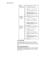
Read Temperatures from Controller |
ü When using a machine that supports this option, PC-DMIS reads the current temperatures from the controller automatically rather than you supplying the data. ü PC-DMIS performs all compensation calculations. The controller only provides the current temperatures. ü During part program execution the Temperature Compensation Setup dialog box does not open. ü The part program does not pause for your confirmation. |
|
Controller Compensates Axes Only |
ü The controller performs compensation of the machine axes itself. ü The inputs for the axes will not be used. ü Part input parameters apply since PC-DMIS still performs compensation for the part. ü During part program execution the Temperature Compensation Setup dialog box does not open. ü The program does not pause for your confirmation. |
|
Controller Comps Axes and Part |
ü The controller performs compensation of both the machine axes and the part. ü The inputs for the axes are not used. ü PC-DMIS does not perform any compensation calculations. ü The input for the part for the material coefficient, reference temperature and origin must still be supplied because PC-DMIS must pass that information down to the controller. ü During part program execution the Temperature Compensation Setup dialog box does not open. ü The program does not pause for your confirmation. |
The Time Remaining display shows the time remaining before the temperature reading takes place. This only displays if you set up a delay period for execution. See “Delay Before Reading Part” on page 7 below.
The Delay Before Reading Part box allows you to specify a period that PC-DMIS will wait during part program execution before reading the Sensors to obtain the current temperatures. If zero is entered then there is no pause.
The Resets to Defaults button updates any previously modified values with the previously saved values. If this is on a DEA machine and a serv1.stp is available then PC-DMIS will read that file.
If you select the Read Temps from Controller method from
Уважаемый посетитель!
Чтобы распечатать файл, скачайте его (в формате Word).
Ссылка на скачивание - внизу страницы.