The power box provides two ways of alarm interfaces for OptiX BWS 320G equipment. One is the interface for critical alarm and the other is the interface for major alarm. When the alarm signal of equipment is output through J9 or J10 on the PDA, the connection is as shown in Figure 1-11.

Figure 1-11 Connection diagram of J9 and J10
When critical alarm occurs in the equipment, the critical alarm terminal will be connected to the critical alarm ground so as to output critical alarm signal. When major alarm occurs in the equipment, the major alarm terminal will be connected to the major alarm ground so as to output major alarm signal. The short-circuit is achieved by using a relay. The principle is shown in Figure 1-12. If there is an alarm, a corresponding relay will close and provide the alarm ground to centralize alarm system.
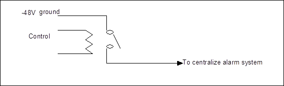
Figure 1-12 Externally connecting alarms
On the PDA, connecting alarm signals to J9 has an equivalent effect to connecting to J10, for each pin of J9 and J10 is short-circuit with each other.
If multiple OptiX BWS 320G cabinets are arranged one by one in a row, alarm cascade mode can be used. That is to say, alarm signals are connected from one cabinet to another, and from the last cabinet to centralize alarm system. The cascade connection between cabinets is shown in Figure 1-13.
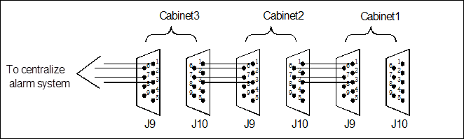
Figure 1-13 External cascade connection of alarms
J11 is the input interface of external alarms:
The PDA provides 6 input interfaces for external alarms. The alarm input function is specially designed for the requirement that the alarms from external systems (e.g. environment monitoring system) comply with remote monitoring. Users can name the 6 ways of alarms, and, with the external systems, achieve remote monitoring on the external alarms.
& Note:
The transmission system is not able to fulfill independently the monitoring function through inputting alarm signals from the external equipment. It should cooperate with external equipment of the user.
Relationship between the pins of J11 interface is shown in Figure 1-14.
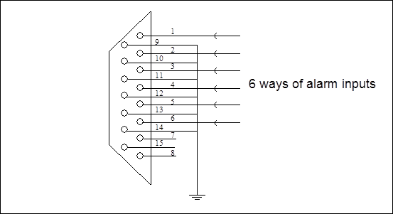
Figure 1-14 Connection of interface J11
External Interfaces of the System.................................................................................................................................. 1
1.1 Schematic Diagram of External Interfaces......................................................................................................... 2
1.2 Interfaces of Data Communication and Equipment Maintenance........................................................................... 3
1.3 Optical Interface............................................................................................................................................. 8
1.4 Power Supply and Alarm Signal....................................................................................................................... 9
Уважаемый посетитель!
Чтобы распечатать файл, скачайте его (в формате Word).
Ссылка на скачивание - внизу страницы.