|
The external interfaces of OptiX BWS 320G Backbone DWDM Optical Transmission System are fully in compliance with the requirements of ITU-T Recommendation. The interface categories include:
(1) SDH optical interface
(2) Communication interface
(3) Subrack power supply interface and PGND ground terminal
This chapter mainly describes the functions of respective external interfaces and the allocation of pins.
1.1 Schematic Diagram of External Interfaces
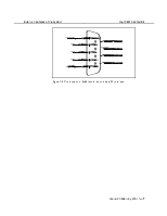
The optical interfaces of OptiX BWS 320G Backbone DWDM Optical Transmission System are set on the handle bar of optical interface board, while other external interfaces are set in the wiring area on the upper part of the subrack in equipment. All external signal cables are connected with the wiring area on the upper part of the subrack. Figure 1-1 is the distribution diagram of the wiring area on the upper part of the subrack in OptiX BWS 320G system.

Note: 1. Ethernet; 2. F&f ; 3. RS-232; 4. Alarm interface; 5. Power interface; 6. Three PHONE interfaces; 7. Fan interface; 8. RS-422; 9. F2; 10. F1; 11. BNC. 12. X.25
Figure 1-1 Distribution diagram of the wiring area on working subrack
1.2 Interfaces of Data Communication and Equipment Maintenance
OptiX BWS 320G system provides various interfaces of data communication and equipment maintenance. The categories of these interfaces are as follows:
(1) Ethernet interface: RJ45 network card module connector used as TMN network management or local management interface.
(2) F&f interface: DB9-type connector that possesses the properties of RS-232 interface and can be used as local management interface.
(3) RS-232 interfaces: DB9-type connectors which are configurable serial interfaces.
(4) ALARM interface: output port of subrack alarm signals.
(5) POWER interface: supply power to subrack.
(6) PHONE interfaces: Three RJ11 phone module connectors used as engineering orderwire interfaces utilizing E1 and E2 bytes of the supervisory channel.
(7) FAN interface: DB9-type fan subrack power alarm interface .
(8) RS-422 interfaces: DB9-type connectors which are configurable serial interfaces provided for users.
(9) F1 interface: DB9-type connector used as co-directional 64kbit/s data communication interface.
(10) F2 interface: DB9-type connector which has RS-232 properties and not available now.
(11) BNC interface: it has the same function of the RJ45 ethernet interface. But these two interfaces can't be used simultaneously.
(12) X.25 interface: DB25-type connector which is used as OAM interface, not available now.
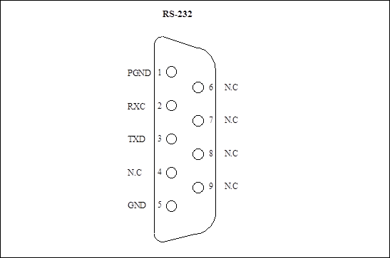
Figure 1-2 Pins allocation of RS-232 interface
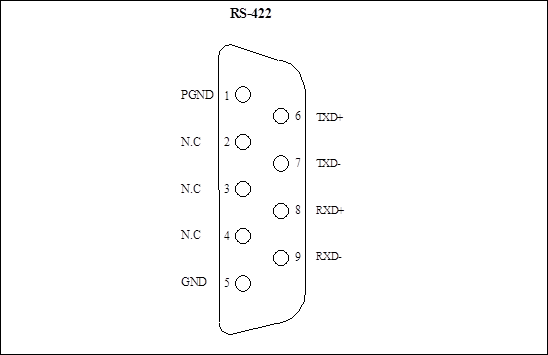
Figure 1-3 Pins allocation of RS-422 interface
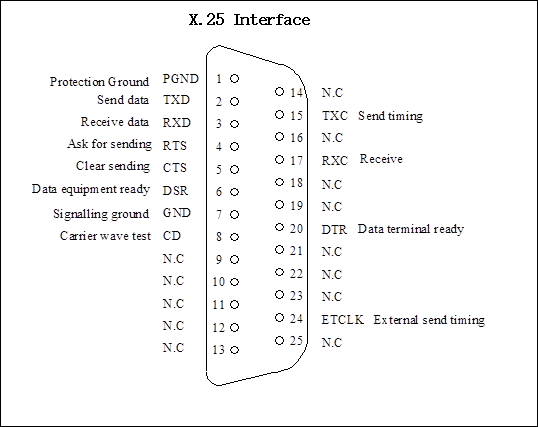
Figure 1-4 Pins allocation of X.25 interface
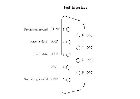
Figure 1-5 Pins allocation of F&f interface
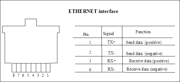
Figure 1-6 Ethernet interface
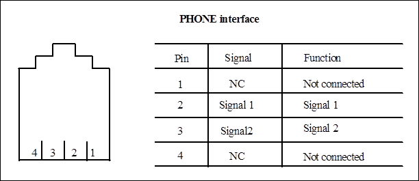
Figure 1-7 Orderwire phone interface
The interfaces of PHONE1, PHONE2 and PHONE3 are the same as that of the orderwire phone in Figure 1-7 and are provided with the same function.
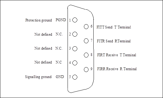
Figure 1-8 Pins allocation of 64kbit/s co-directional data (F1) interface
1.3 Optical Interface
FC/PC interface, which is located on ODF subrack.
SC/PC interface, which is located on the handle bar of optical interface board.
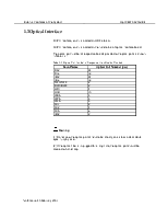
The optical port number of respective boards provided with optical ports is shown in Table 1-1:
Table 1-1 Optical Port Number of Respective Main Boards Provided
|
Baord Name |
Optical Port Number (pcs) |
|
D32 |
34 |
|
D16 |
18 |
|
M32 |
34 |
|
M16 |
18 |
|
TWC/TWF |
2 |
|
RWC/RWF |
2 |
|
LWC |
4 |
|
OCU |
10 |
|
WBA |
3 |
|
WPA |
3 |
|
WLA |
3 |
|
SC1 |
2 |
|
SC2 |
4 |
|
SCA |
6 |
|
MS2 |
2 |
![]() Warning:
Warning:
(1) Do not view the optical port of handle bar directly, so as to avoid accidental eyes injury by laser.
(2) If the optical fiber is unplugged for a long time, the optical port should be covered with dust cap.
1.4 Power Supply and Alarm Signal
1. Introduction of power box
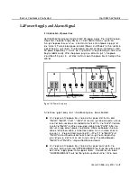
OptiX BWS 320G employs standard -48V DC power supply. The -48V DC power, output from the power supply device, is transmitted to the working subrack through the power box, which will also monitor the alarms of power supply and environment. There are two power sockets (Power1 and Power2) at the interface area of the working subrack. The two power sockets can be connected with -48V DC power respectively. In normal working condition, the protective ground should be grounded soundly. When the power plug is pulled out or put in, the power should be off. Figure 1-9 illustrates the front view of the power box at the top of the cabinet.
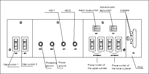
Figure 1-9 Power box panel
In the following part every item in the above figure will be elaborated.
n On the panel of the power box, there are four power distribution lead, "PGND", "BGND"," -48V1", "-48V2". When making cable connection, make sure that the blue cable is connected to the "-48V1" or the "-48V2"; the black one to the "BGND", and the yellow-green cable to the "PGND". After the cabinet is supplied with power, the potential difference between the blue cable and the black cable, is to be measured with a multi-meter so as to ensure it is in the permitted range (-38.4V ~ -57.6V). The "BGND" and "PGND" are combined outside the cabinet through the corresponding grounding wire, and that is called joint grounding. The cable between "BGND" and "PGND" is not permitted to be removed.
Уважаемый посетитель!
Чтобы распечатать файл, скачайте его (в формате Word).
Ссылка на скачивание - внизу страницы.