3 —It is set to lower position, when normal –48V power is input. It is set upper position to shield common over-voltage alarm(just for some special area).
4 — reserved.
3. Low-voltage protection board LVC
The main functions of LVC(Low Voltage Control Unit) are as follows:
1) Shutoff low-voltage power supply
When LVC detects that the -48V power voltage input from outside is lower than a specific preset value, it will immediately shut off the -48V power to this rack so services switching can be performed very rapidly.
2) Turn on the power supply automatically
As soon as LVC detects that the -48V power supply input from outside resumes to normal, it will automatically switch on the -48V power supply to this rack and the rack restarts normal work.
4. Over-voltage protection unit OPU
The main function of OPU (Over-voltage Protection Unit) is: when lightning happens, OPU board can make fast response to the transient high voltage generated on the -48V power supply lines and restrict the power supply voltage of the rack within an acceptable range, thus ensuring a safe operation of the equipment.
1.3 ODF Subrack
Inside the rack of the OptiX BWS 320G system there is a large number of optical fibers, making it difficult for expansion or maintenance. And the intertwist of optical fibers may lead to the bending of some fibers, which in turn affects the normal traffic. To fix the optical fibers inside the rack and reduce the operation of the fibers, it is necessary to add one top ODF subrack, as shown in Figures 1-12.
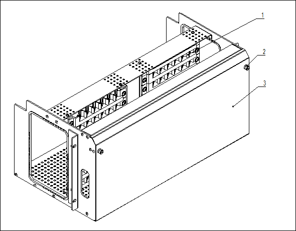
Note:1. Flange. 2. Latch. 3. Panel.
Figure 1-12 Top ODF subrack
The top ODF subrack is installed on the top of rack, closely to the power box, each rack is configurated one ODF subrack, the top ODF subrack has 96 position hole to install flange.
1.4 Fan Subrack
Each equipment subrack of OptiX BWS 320G system contains a fan subrack. The fan subrack is composed of fans and dust-proof screens. Dust-proof screens can be taken out and rinsed directly. The fan subrack structure is shown in Figure 1-13.
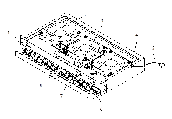
NOTE:1.Dust-proof screen; 2.Fan; 3.Fan fuse; 4.Input/output port of fan; 5.Fan power. 6.Switch; 7.Indicator; 8.Handle.
Figure 1-13 Fan subrack
Rackx....................................................................................................................................................................... 1
1.1 Rack Structure............................................................................................................................................... 1
1.1.1 Structure Diagram................................................................................................................................. 1
1.1.2 Physical Parameters.............................................................................................................................. 3
1.2 Power Box.................................................................................................................................................... 4
1.2.1 Instruction of Power Box....................................................................................................................... 4
1.2.2 Circuit Board in the Power Box.............................................................................................................. 5
1.3 ODF Subrack............................................................................................................................................... 14
1.4 Fan Subrack................................................................................................................................................. 15
Уважаемый посетитель!
Чтобы распечатать файл, скачайте его (в формате Word).
Ссылка на скачивание - внизу страницы.