The method that boards of subrack gain power individually is described below:
First, external -48V DC power can be inducted into power box at the top of rack through power cable. Then, the -48V power is distributed to every subrack through the 4 subrack power switches and the power distribution adapter (PDA). After that, each board on the subracks gain proper power from proper location at the mother board through its own power pin, and the built-in secondary power module on each board converts the power into the operation voltage required by each chip on the board.
1.2.2 Circuit Board in the Power Box
The power box installed at the top of the rack is used to distribute -48V DC power. To provide power of high stability for the equipment and improve electricity supply safety, power filters and over-current and over-voltage protection devices are equipped. Besides, the power box is equipped with four units: A power monitoring unit (PMU), which features voltage monitoring, temperature monitoring, and alarm import and export, a power distribution adapter (PDA) unit, and an over-voltage protection unit (OPU) to prevent lightning shock and voltage impulse, low voltage control (LVC) unit which provides low voltage protection. The locations of all the circuit boards in the power box are shown in Figure 1-3. The function diagram of the power box is shown in Figure 1-4.
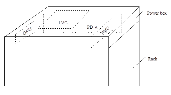
Figure 1-3 Position schematic diagram of respective boards in the power box

Figure 1-4 Function block diagram of power box
Accoding to the block diagram, Functions of the power box are:
n Power general switch: 2
Transmission equipment can be powered by two mutual-backup power supplies, and each power supply is provided with a general switch.
n Bridge rectifier: 2
The function of bridge rectifiers is to integrate the two -48V power supplies into a whole unity. The bridge rectifiers can separate the two power supplies and prevent from reversed connection of the negative and positive poles. The two bridge rectifiers are connected in parallel and act as mutual backups.
n Filter: 1
The filter is equipped with two levels of LC filtering circuit and has very good filtering effects.
n Subrack power switch : Totally 4
Magnetic circuit breaker is used as subrack power switch, and two such switches are available for each subrack. These two switches work in mutual backup mode.
n PDA board : 1
It is used to distribute the -48V power supply, -48V ground. It has over-current protection function, meanwhile it provides various electrical interface to external equipment.
n PMU board : 1
Its functions include: generate ringing current, monitor the two lines of -48V voltage, monitor the temperature inside the rack, access of six paths of alarms, output two paths of alarms, communicate with the main control board.
Because there is no direct communication interface with subrack on the PMU board, communication method between PMU board and subrack is as follows. First, signal of subrack is induced into corresponding interface on PDA board. Then, the signal is induced into PMU board through the interface between PMU board and PDA board. After this, the signal is monitored and controlled by PMU board.
n LVC board : 1
When the LVC board detects that the -48V power voltage input from outside is lower than a specific preset value, it will immediately shut off the -48V power supply to this rack so as to perform quick switching. As soon as LVC board detects that the -48V power voltage input from outside resumes to normal, it will connect through the -48V power supply to the rack.
Уважаемый посетитель!
Чтобы распечатать файл, скачайте его (в формате Word).
Ссылка на скачивание - внизу страницы.