|
FIGURE 1. Film thickness profiles for Cu-Si films obtained at dTS: 1 — 100; 2 — 140 mm; and Ti-Si films obtained at dTS: 3 — 55; 4 — 90; 5 — 190 mm |
FIGURE 2. Critical indentation load vs. Ti-Si film thickness. dTS: «+» — 55 mm; «°» — 90 mm; «·» — 90 mm with the transition layer |
TABLE 1. Characteristics of the thin films
|
Film |
Distance dTS, mm |
55 |
75 |
90 |
100 |
140 |
170 |
240 |
|
C-Si, 10 shots |
Thickness t, mm |
0.202 |
0.179 |
0.158 |
0.051 |
|||
|
Roughness Ra, nm |
83 |
82 |
63 |
8 |
||||
|
Nanohardness H, GPa |
1.772 |
4.010 |
5.762 |
19.441 |
||||
|
Young modulus E, GPa |
37 |
70.8 |
96 |
119 |
||||
|
Cu-Si, 3 shots |
Thickness t, mm |
0.117 |
0.093 |
0.08 |
0.033 |
|||
|
Roughness Ra, nm |
5.35 |
4.38 |
3.72 |
3.3 |
||||
|
Nanohardness H, GPa |
5.127 |
6.262 |
5.361 |
5.934 |
||||
|
Young modulus E, GPa |
134 |
128 |
139 |
130 |
||||
|
Ti-Si |
Thickness t, mm |
0.23 |
0.13 |
0.068 |
||||
|
Nanohardness H, GPa |
6.51 |
7.15 |
55.15 |
|||||
|
Young modulus E, GPa |
86.1 |
123.8 |
318.1 |
|
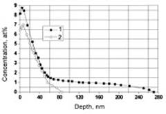
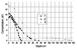
HPIB-STIMULATED MASS TRANSFER OF IMPLANTED DOPANT IN MATERIAL SURFACE LAYERS The mass transfer of previously implanted dopant under the HPIB irradiation was studied earlier in [2]. Below, the possibilities of the combined method to control elemental and phase composition of surface layers at multiple implantation-irradiation cycles are considered. Investigations were carried out for the case of Ti implantation into Si and Fe samples on the facility for combined materials treatment [2] containing the implanter «Raduga» and source of HPIB (70 % H+, 30 % C+, 500 keV, 100 ns). The experimental protocol was as follows. After repetitively-pulsed implantation of Ti (Ti+n, n=1–3, 50 keV, 400 ms, 50 pps) with the dose of ~1×10¹⁷ ions/cm2, the samples were irradiated with two HPIB pulses of the given energy density. Then, this cycle was repeated. The number of these cycles being done in one technological operation was up to 8. The operating vacuum level, ~(3–5)´10–6 torr, was provided by the cryogenic pumping system. For determination of elements concentration profiles, the method of Rutherford backscattering of helium ions (1.5 MeV energy) was used. In Figure 3 the concentration profiles of Ti in the Ti-Si and Ti-Fe systems are presented. For the Ti-Si system, it is seen that after the 4 implantation-irradiation cycles, storage of the implanted dopant is accompanied by the increase of penetration depth up to ~270 nm (compared to the initial depth of ~90 nm). For the Ti-Fe system, the depth of Ti diffusion after the 4 performed cycles is ~75 nm, and after the 8 such cycles, it achieves ~155 nm that exceeds the initial implantation depth by more than 5 times. Typical feature of the mass transfer is almost linear growth of the depth of Ti embedding with increasing number of HPIB irradiation pulses for both Ti-Fe and Ti-Si systems. At the same time, the depth of dopant penetration remains less than the calculated thickness of melted layer. This can be conditioned by decreasing liquid-phase lifetime and reducing dopant concentration gradient with depth below the surface that influence on the diffusion process.
FIGURE 3. Ti concentration profiles over the depth in Si and Fe samples. For the Si sample (left plot): 1 — after 4 cycles of Ti implantation (~1017 ions/cm2) and HPIB irradiation (~1.6 J/cm2, 2 shots); 2 — after initial Ti implantation. For the Fe sample (right plot): 1 — after initial Ti implantation (~1017 ions/cm2); 2 — after 4 cycles of Ti implantation and HPIB irradiation (~1.8 J/cm2, 2 shots); 3 — after 8 cycles REFERENCES 1. Renk T. J., Provencio P. P. Prasad, S. V. et al., Proceedings of the IEEE 92, 1057–1081, 2004. 2. Petrov A. V., Ryabchikov A. I., Stepanov I. B. et al., Surf. Coat. Technol., 158-159, 170–173, 2002.
|
|
* The work was supported in part by the Ministry of Education of Russian Federation (grant TO 2-07.5-708) and Civilian Research and Development Foundation (Project RU-P2-2573-TO-04). |
Уважаемый посетитель!
Чтобы распечатать файл, скачайте его (в формате Word).
Ссылка на скачивание - внизу страницы.