 . (19)
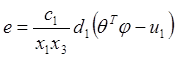
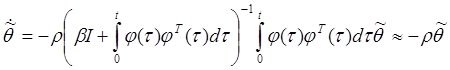
Analysis of the error model (19) motivates the following structure of adaptive controller
![]() (20)
(20)
where the vector
of adjustable parameters ![]() is generated by the
adaptation algorithm with improved parametric convergence [6].
is generated by the
adaptation algorithm with improved parametric convergence [6].
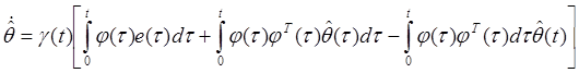 (21)
(21)
with gain function
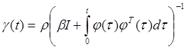 ,
, ![]()
where ![]() is a small constant.
is a small constant.
Taking
(20) in (19) and transforming equation (21) we obtain the parametric error ![]() and stabilization error
and stabilization error ![]() models of the closed loop
system:
models of the closed loop
system:
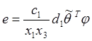 , (22)
 . (23)
Thus adaptive control law proposed is described by equations (21):
(13), (14) – state observer;
(20) – adjustable controller;
(21) – adaptation algorithm.
Properties of the closed loop system are established by the following
proposition: for any ![]() and
any initial conditions all the signals in the closed loop system consisting of
the plant (7), (9), state observer (13), (14) adjustable controller (20) and
adaptation algorithm (21) are bounded and additionally
and
any initial conditions all the signals in the closed loop system consisting of
the plant (7), (9), state observer (13), (14) adjustable controller (20) and
adaptation algorithm (21) are bounded and additionally ![]() as
as ![]() asymptotically if
elements of matrix
asymptotically if
elements of matrix  are
linearly independent. Moreover the rate of parameter convergence and the
speed of the closed-loop system can be arbitrary increased with increasing
parameter
are
linearly independent. Moreover the rate of parameter convergence and the
speed of the closed-loop system can be arbitrary increased with increasing
parameter ![]() that results from equation (23).
that results from equation (23).
Remark 2: In spite of perfect
convergence some integrals in the expression (21) grow unboundly as ![]() . Therefore in practice
resetting of integration in definite time period has to be used
. Therefore in practice
resetting of integration in definite time period has to be used
3. Nonlinear torque control
At the stage of torque control synthesis we assume that engine
parameters ![]() ,
, ![]() ,
, ![]() are determined in the course of experiment
and a priory known.
are determined in the course of experiment
and a priory known.
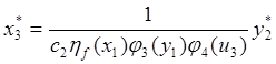
To provide asymptotic convergence of indicated torque according to
expression (12) let us define the reference signal ![]() using
equation (10) as
using
equation (10) as
![]() (24)
(24)
where ![]() is the reference signal of air pressure in
the intake manifold. Let us express
is the reference signal of air pressure in
the intake manifold. Let us express ![]() as
as
 . (25)
Now we introduce
error signal ![]() where
where ![]() is
the state variable of reference model
is
the state variable of reference model
![]() ,
, ![]() . (26)
. (26)
Let us define the error model as
![]() (27)
(27)
that provides asymptotic tracking of signal
![]() . Assuming that the
subsystem described by equation (6) is stable (i.e. engine works at stable
regimes) and analyzing error model (27) we obtain the following control law:
. Assuming that the
subsystem described by equation (6) is stable (i.e. engine works at stable
regimes) and analyzing error model (27) we obtain the following control law:
 (28)
(28)
or
 . (29)
Thus the torque regulator is presented by equations (25) and (29).
For any ![]() and any initial conditions all
the signals in the closed loop system consisting of the stable plant (6), (8),
(10) and regulator (25), (29)
and any initial conditions all
the signals in the closed loop system consisting of the stable plant (6), (8),
(10) and regulator (25), (29) ![]() as
as ![]() asymptotically.
asymptotically.
4. Simulation
To confirm validity of engine model and illustrate the work of closed loop system MathLab/ Simulink software is used. Engine parameters and approximations of static functions of the engine (Ford 840 Ci, motronic) model are presented in tables 1 and 2 [10]. Parameters of air to fuel ratio controller (13), (14), (20), (21) and torque controller (25), (29) are presented in table 3.
Table 1. Engine parameters. Table 2. Static functions.
Уважаемый посетитель!
Чтобы распечатать файл, скачайте его (в формате Word).
Ссылка на скачивание - внизу страницы.