|
|
|
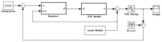
Fig. 1. Structural scheme of system. |
A block “ICE Model” contains transfer function Wφ(p) of the regulated object according to regulating influence φ(t). As a regulating influence the angle of the throttle vale opening was chosen. A present index has the largest coefficient of gain (unlike the angle of spark advance and cycle fuel delivering) and a little lagging, that allows to effect on the engine in all conditions of the performance and ensures the most accurate controlling.
|
a) |
b) |
|
c) |
d) |
|
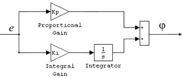
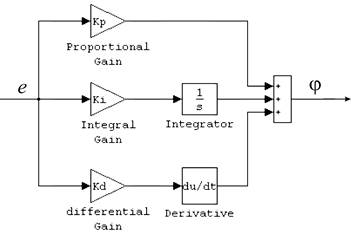
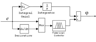
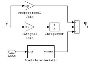
Fig. 2. Types of applied regulators. |
|
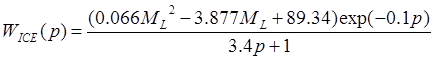
The meanings of the coefficients of the transfer function of the engine were determined experimentally according to a boiling curve, obtained by means of stepping changing of the angle of the throttle valve opening. The influence of loading condition on the meaning of the coefficients of the transmission function Wφ(p) is defined experimentally (the influence of speed condition was not considered as it can be changing insignificantly). For this purpose the series of experiments was made to determine indexes of transition process with the load meaning 0, 25, 50 and 100% of the maximum one. As a result the transfer function of the engine load is following:
|
where ML – the moment of load resisting, The noise power is 0,3% of the useful signal and emulate such properties of the engine as twisting oscillations and unevenness of rotating frequency during the cycle. The efficiency of the laws of regulation was defined by comparison of the main indexes of the quality of transition processes of the automatic control system (tab.).
According to the results of designing the most effective process is the automatic control system based on two impulse regulator. It can be explained by that very regulator allows combining the advantages of both closed and opened controlling systems. The efficiency of the performance of the PID controller is higher, but a little, that can be resulted by the influence of the noises on the differential channel of controlling. The applying of the fuzzy logic controller is also a little increase the quality of transition processes. It is because we can operate only with proportional and differential constituent of the signal of the disagreement e, as the meanings to which they must trend to nought are known. The meaning of the integral constituent determining the last throttle position is known because it depends on the load quantity on the engine, which is changing regularly. The using of the fuzzy logic controllers is the most effective in the cases when desired changing laws of object regulating coordinates during the exploitation process are known. The following step will be connected with experimental check of obtained results. |
||||||||||||||||||||||
DEVELOPMENT OF AN EXPERIMENTAL PROTOTYPE
The principle scheme of the controlling systems is shown on fig.3 and includes the systems of regulating by the fuel delivering, ignition and throttle valve.
|
|
|
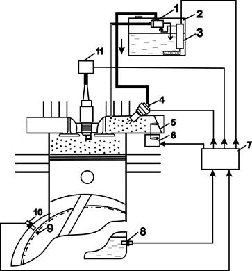
Fig. 3. Principle scheme of the controlling systems. |
As a drive (6) of the throttle valve (5) the stepping engine is used. According to the position of its shaft the position of the throttle valve can be defined. The rotating frequency and the position of crankshaft are determined by means of inductive sensor (10), fitted close to the toothed gear rim. As a mark of top dead center (TDC) a lug is used on the flywheel and its passing by the sensor makes the increased amplitude of the signal in comparison with the others teeth.
The fuel injects into the inlet passage by electromagnet nozzle (4) under the pressure of 3 bars, crated by electrical fuel pump (3) fitted in the tank (2). A drop of the fuel pressure is supported by stabilizer (1). The mixture composition is stochiometric.
The ignition system includes the ignition coil (11) fitted directly on the plug.
The controlling indexes of the system are duration and the moment of fuel injection, the angle spark advance and the position of the throttle valve. The meanings of these indexes are formed in the control block (7).
Уважаемый посетитель!
Чтобы распечатать файл, скачайте его (в формате Word).
Ссылка на скачивание - внизу страницы.
 ,
, – algebraic operator of differentiation.
The meaning of the constants of the time and lagging according to the load
can change a little and are accepted to be constants.
– algebraic operator of differentiation.
The meaning of the constants of the time and lagging according to the load
can change a little and are accepted to be constants.