ELECTRICAL CONTROL SYSTEM OF THE SHAFT ROTATING FREQUENCY OF ONE-CYLINDER INTERNAL COMBUSTION ENGINE
Department of Internal Combustion Engine
Vladimir State University
Gorkogo st.87, Vladimir, 600000, RUSSIA
Tel: +7(4922)279-940, E-mail: -sandy-@mail.ru
ABSTRACT
In present work the testing results of the closed system of automatic regulating of the shaft rotating frequency of one-cylinder Internal Combustion Engine T-520 (production of “Tulamashzavod”) for the electro generator drive. The peculiarity of present system is the application of two-impulsive regulator based on new method of indirect determining of the engine loading.
The most part of one-cylinder Internal Combustion Engines producing at present time are used as a drive for the generator installations. The main demand made of Internal Combustion Engine when working with generator – the keeping necessary of the shaft rotating frequency in any load. The given task is solved by the way of installation automatic regulating of the shaft rotating frequency on the engine. Most of using regulators are the mechanical ones, realizing the simple laws of regulation. The attempts of qualifying the regulation by the way of their construction improvement lead to the increasing of the system cost and reducing its reliability. At the same time the regulating process of exactly one-cylinder engines is the most difficult. The difficulties are connected with such its peculiarities as unevenness of rotating frequency during the cycle, low frequency of controlling influences (once in two revolutions of the shaft), inter-cycling not identity, etc. Separately should be noticed such problems of the petrol engines as admissions of igniting and inertness of making mixture process. As a result the quality of regulating processes is greatly getting worse.
To increase the performance quality system of automatic regulating is necessary both the improving of executive devices of the system and the application more complex regulating laws. Analyzing of literature shows that most modern control engine systems (fuel, ignition, cooling and others) are electrical, controlling by microprocessor block. The applying of microprocessor systems, unlike mechanical or analog electrical ones, is enabling to realize more complex laws and algorithms, providing high quality of regulation.
The main purpose of the system of automatic regulating – is keeping needed meaning of the rotating frequency or changing it in definite program given before or entering from without during the process of system operation. The most important stage of automatic regulating system planning is determining its structure and the choice of more effective laws of regulating, which enable to get the best qualitative indices. For this aim the mathematical model of system of automatic regulating allowing determining the type of transitional process of the system according to the regulating laws and the character of load changing was developed.
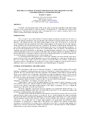
Structural scheme of system is shown on fug.1. It consists of the following blocks: “Setting device”, “Regulator”, “Load Model”, “ICE Model”, “ICE delay” and “Noise”.
“Setting device” serves to form the setting influence (n0) the meaning of which is necessary to keep. The availability of the reverse connection enables to define disagreement e = n0 - n. The quantity of disagreement is given to the regulator, determining needed influence on the object of regulating. To come to naught the disagreement e, the system works this way all the time.
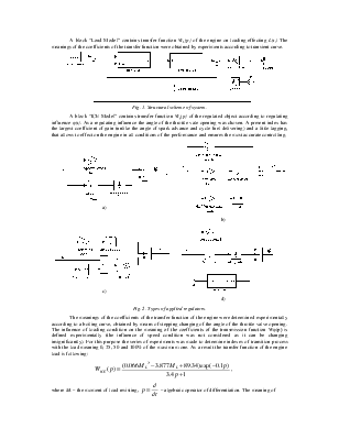
The block “Regulator” realized the following regulating laws: proportional-integral (PI) (fig. 2, a), proportional-integral-differential (PID) (fig.2, b), based on fuzzy logic (fig.2, c), two-impulse (according to the declination of rotating frequency and loading) (fig.2, d).
The tuning of the coefficient PI and PID of the regulators was producing to ensure minimum time of the traditional process when limited oscillatory movements [1]. In two- impulse regulator the impulse considering the load on the engine is the functional dependence of the opening angle of the throttle valve on the load and rotating frequency resulted during statistical condition. In fuzzy regulator three linguistic variable quantities were used – two of input and one of output. Input quantities were proportional and differential signals constituencies of disagreement e, output angle of the throttle valve opening. The meaning of proportional constituency was described by five triangle terms, a differential one by three. To describe output quantity five triangle terms were used. The rule base contained 28 production rules, connecting linguistic variable quantities. Defuzzification was provided by algorithm of Mamdani [2].
A block “Load Model” contains transfer function WL(p) of the engine on loading effecting L(t). The meanings of the coefficients of the transfer function were obtained by experiments according to transient curve.
Уважаемый посетитель!
Чтобы распечатать файл, скачайте его (в формате Word).
Ссылка на скачивание - внизу страницы.