where ![]() τ=l/V; l– distance from calorifers up to detectors of temperature, m; V
– rate of movement of air, m/sec.
τ=l/V; l– distance from calorifers up to detectors of temperature, m; V
– rate of movement of air, m/sec.
Differential equations (2.2.2), (2.2.4), (2.2.5), introduced in a Cauchy normal form, together with the finite equation (2.2.9) and difference equation (2.2.3), produce a following dynamic model of calorifer plant.
Deriving of transfer functions on the relevant channels.
In the obtained mathematical model of calorifer plant controlled quantities are the temperature of air in shaft Tstv(t) and the temperature of waste heat-transfer agent T2(t). As control actions are accepted: the flow of incoming heat-transfer agent G1(t) and the air-flow rate, passing through calorifers G2(t). Disturbing effects are T'V(t) – temperature of outdoor air and Т1(t) – temperature of incoming heat-transfer agent.
Having taken into account influence of the given parameters against each other, the block diagram of calori-fer plant as control object, which one serves for the further analytical researches of the setting, has been offered.
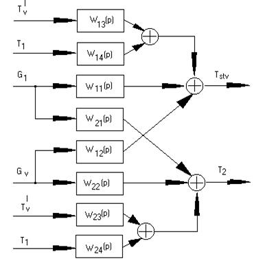
Block diagram of calorifer plant as control object
Entering notation conventions of coefficients at the relevant magnitudes we received following transfer functions on control and agitation channels.
Calculation and simulation of control system.
Αs a basis for the local automatic control system of regulatory type we select the automatic control system of temperature from shaft of stack. Regulation we shall fabricate, changing the flow of primary heat-transfer agent (heated water), with correction of a runout on temperature, which one will vary under action of temperature of a free air and temperature of primary heat-transfer agent.
Except for object models on the appropriate channel it is necessary to select an actuating device and to calculate all parameters which are included in its transfer function.
The transfer function of the final control
element displays changing of a rotation angle of a valve at changing of a flow
of matter. By experimental way it has been fixed, that ![]() .
.
Calculation of the obtained automatic control system of regulating is concluded in accounting of customizations of a controller, and also theoretical calculation of the compensator on the channel of an agitation.
Calculation of customizations of a controller.
As it mentioned above, calorifer plant on a circuit interesting us is an aperiodic link. Outgoing from these reasons, we select PI - controller, implementation which one it will be realized on baseline of (broached) proembroidered standard algorithms implemented in control unit Simatic S7-300.
Transfer function of the control object: 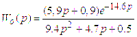 ,
, ![]()
Transfer function of PI – regulator: ![]()
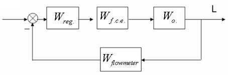
The block diagram of system of automatic regulation of a level without taking into account disturbations
Calculations of settings of a regulator on
a base of a desirable index of oscillation ![]() it will be carried out with the help of mathematical pack MATLAB.
it will be carried out with the help of mathematical pack MATLAB.
We find out: 
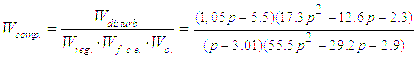
Calculation of compensator.
For calculation of the compensator we shall discover indispensable transfer functions.
![]()
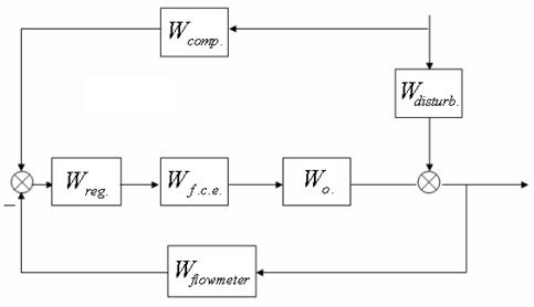
Block diagram of system of automatic regulation of a level with disturbance for calculation of the compensator
For calculation of a transfer function of the compensator it is used the equivalent conversions of links, in particular - rules of transposition through the summator.
Transfer function of the compensator for such system:
Simulation of the automatic control system of regulating.
Simulation of automatic control systems of regulating obtained above was led with the help "MATLAB" Simulink.
Уважаемый посетитель!
Чтобы распечатать файл, скачайте его (в формате Word).
Ссылка на скачивание - внизу страницы.