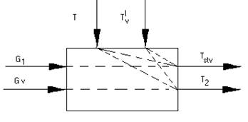
Schematic model of calorifer setting
Determine of mathematical model of calorifer plant
In a basis of the mathematical description
of the processes running in setting lays the generalized equation of thermal
balance:  ,
,
where ΔF - fluctuation of an entalpy; Q - thermal streams.
Let's break calorifer setting into three interconnected sectors with specific character of the physical phenomena in them: area of calorifer plant with established heat exchange devices; the chamber of mixture; section of a shaft from its mating to mixing chamber up to a setting point of temperature detectors (.-50 m).
The first section three tandem sections divide in thermal reservoirs is representable: a) the internal cavity of the fixed calorifers, the filled the overheated water; b) metal wall of calorifers; c) air space of calorifers.
The differential equation of a heat balance for the first reservoir looks like:
![]()
where Tsr(t) - average value of
overheated water temperature, defined by the formula: ![]()
С1 – specific heat capacity of superheated water, kcal / kg *0С; G1(t) – the flowof overheated water through calorifers, kg / hour; D1 – quantity of overheated water in an internal cavity of calorifers, kg; Т1(t), Т2(t) – temperature of overheated water on an input and an output from heaters, accordingly, 0С; ТС(t) – temperature of a metal wall of calorifers, 0С; КС – heat-transfer coefficient from water to walls of tubes of calorifers, kcal /m2*hour*0С; FС – internal surface of all tubes of fixed calorifers, м2; t – current time, sec.
The differential equation of a heat balance for the second reservoir looks like:
![]()
where КV – heat-transfer coefficient from walls of a calorifer to heated air, kcal /m2*hour*0С; FV – heat-exchange surface of the fixed heaters, m2; СС – specific heat capacity of a wall, kcal /kg*0С; DС – weight of a metal wall, kg; Т'V, T''V – temperature of cold and heated air, 0С;
The differential equation of a heat balance for the third reservoir looks like:
![]()
where GV(t) – the flow of air through calorifers, kg/hour; СV - specific heat capacity of air, kcal/kg*0С; DV – quantity of heated air in volume of calorifers, kg.
The heat-transfer coefficient from water to a wall of calorifer КС is definable from following expression:
![]()
where λ – heat conduction coefficient of walls of
a calorifer, kcal/m*hour*0С; d – internal diameter of tubes of
calorifers, m; ![]() - Reynolds's criterion;
- Reynolds's criterion; ![]() - Prandtles's criterion;
- Prandtles's criterion;
where ω – rate of overheated water in tubes of calorifers, m/hour; α – thermal diffusivity of superheated water, m2/hour; ν – kinematic factor of viscosity of superheated water, m2/hour.
Heat-transfer coefficient from a wall to
air: 
where δ – thickness of walls of tubes of a
calorifer, m; КО – factor of fining, representing the ratio
of an internal surface of tubes of a calorifer to a surface of all ribs; К –
heat-transfer coefficient of a calorifer: ![]()
where a, n, m – empirical factors; ν, ρ – rate of movement of air in effective cross-section of a calorifer and its density, m/hour; кг/м3; ω – rate of movement of superheated water in section of a calorifer, m/hour.
The second section, or mixing
chamber, joint with shaft, it is possible to consider practically as an instantaneous
element: ![]()
where Тsm(t) – temperature of air after the mixing chamber, 0С; Gmax(t) – the maximal flow of air through the mixing chamber, kg/hour;
The third section - a section of shaft up
to a setting point of temperature detectors can be taken into account by
introduction of transportation lag: ![]()
Уважаемый посетитель!
Чтобы распечатать файл, скачайте его (в формате Word).
Ссылка на скачивание - внизу страницы.