Contents
1 Network Topology and Networking Capability 1-1
1.1 NE Description 1-1
1.1.1 TM 1-1
1.1.2 ADM 1-2
1.1.3 MADM 1-3
1.2 Network Topology 1-6
1.3 Networking and Grooming Capability 1-9
1.3.1 Networking Capability 1-9
1.3.2 Grooming Capability 1-10
Figures
Figure 1-1 Functional block diagram of TM 1-1
Figure 1-2 Hardware configuration of the OptiX OSN 9500 when serves as an STM-64 TM 1-2
Figure 1-3 Functional Block diagram of ADM 1-2
Figure 1-4 Hardware configuration of the OptiX OSN 9500 when serves as an STM-16 ADM 1-3
Figure 1-5 Hardware configuration of the OptiX OSN 9500 when serves as an STM-64 ADM 1-3
Figure 1-6 Functional Block diagram of MADM 1-4
Figure 1-7 Hardware configuration of the OptiX OSN 9500 when serves as an STM-64 MADM 1-4
Figure 1-8 Hardware configuration of the OptiX OSN 9500 when serves as an STM-16 MADM 1-5
Figure 1-9 Hardware configuration of the OptiX OSN 9500 when serves as STM-64/STM-16 MADM 1-5
Figure 1-10 Hybrid network of the OptiX OSN 9500 and other equipment 1-9
Figure 1-11 Hybrid network of the OptiX OSN 9500, the OptiX 10G and the OptiX OSN 3500 1-10
Figure 1-12 Grooming capability of the OptiX OSN 9500 1-11
Tables
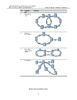
Table 1-1 Network topology 1-6
This chapter introduces NEs of the OptiX OSN 9500, as well as its networking application and grooming capabilities. It includes:
n NE description
n Network topology
n Networking and grooming capability
1.1 NE Description
The OptiX OSN 9500 is a kind of optical core switching (OCS) equipment. It supports hybrid configuration of conventional terminal multiplexer (TM), add/drop multiplexer (ADM), and multiple add/drop multiplexer (MADM).
1.1.1 TM
The principal function of TM is to multiplex low-rate signals into high-rate SDH signals, to cross connect the line signals with low-rate SDH signals, and to demultiplex high-rate SDH signals into low-rate signals.
Figure 1-1 Functional block diagram of TM
TM is used as the terminal of a point-to-point network, a chain network or the end of a ring with chain network.
Figure 1-2 shows a hardware configuration when the OptiX OSN 9500 serves as a TM. The JL64 board can be inserted in slots IU01–IU40 to transmit and receive signals at a certain rate. Configure boards in other slots based on service requirements.
Figure 1-2 Hardware configuration of the OptiX OSN 9500 when serves as an STM-64 TM
1.1.2 ADM
ADM is the most widely used NE. It can add/drop SDH signals by integrating synchronous multiplexing and digital cross-connection functions into a whole. Besides the functions of TM, ADM also provides the cross-connection of line signals, and between line signals and low-rate SDH signals. For example, the accessed STM-1 SDH signals can be multiplexed and connected to line signals of two directions. The line signals of two directions can be interconnected.
The structure of ADM is similar to two back-to-back TMs, as shown in Figure 1-3.
Figure 1-3 Functional Block diagram of ADM
ADM is widely used in chain, ring and hub networks.
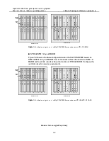
Figure 1-4 shows a hardware configuration when the OptiX OSN 9500 serves as an STM-16 ADM. Insert two JL16 boards in any two of slots IU01–IU40 to transmit and receive STM-16 optical signals of two directions. Then, configure boards in other slots based on service requirements.
Figure 1-4 Hardware configuration of the OptiX OSN 9500 when serves as an STM-16 ADM
Figure 1-5 shows a hardware configuration when the OptiX OSN 9500 serves as an STM-64 ADM. Insert two JL64 boards in any two of slots IU01–IU40 to transmit and receive STM-64 optical signals of two directions. Then, configure boards in other slots based on service requirements.

Figure 1-5 Hardware configuration of the OptiX OSN 9500 when serves as an STM-64 ADM
Уважаемый посетитель!
Чтобы распечатать файл, скачайте его (в формате Word).
Ссылка на скачивание - внизу страницы.