These can be in the form of previously generated Split lines, Split Surfaces and Die blocks. In this example, Split lines, Split Surfaces and Die Blocks will be automatically created by the wizard and the object information area highlights the selection of the product only.
· Select ‘Next’
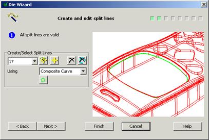
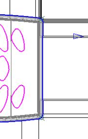
The second page allows the user to create and edit split lines. The wizard has automatically generated the split lines to be used for this model.
Each split line is numbered and can be selected, and modified if necessary, from the Pull Down list. As a split curve is selected, it is displayed in the Die Wizard graphic window.
The model can be dynamically manipulated in the Die Wizard graphic window in the same way it can be manipulated in the PowerSHAPE graphic window.
· Select ‘Next’ to continue.

This form gives the user the opportunity to change or create fill-in surfaces.
This is not required.
· Select ‘Next’ to continue.
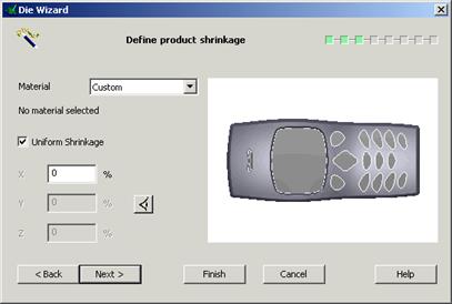
This page allows the user to specify product shrinkage; the amount by which the mould cavity increases to allow for shrinkage.
The drop down list displays the abbreviated names of the materials; when a material is selected, the full name of the material is displayed below. A predefined value (dependent on the material selected) will be automatically inserted into X, Y and Z. Uniform Shrinkage can be switched off to enable the user to set different shrinkage factors for X, Y and Z.
![]()
· From Material Drop down select ‘ABS’.
· Select ‘Next’ to continue.
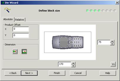
![]() This page of the wizard allows the user to specify block size for
the die inserts. Size can be set using overall dimensions for the block
or by setting a minimum land dimension.
This page of the wizard allows the user to specify block size for
the die inserts. Size can be set using overall dimensions for the block
or by setting a minimum land dimension.

· Set a block length of 200 and a width of 100.
· Select ‘Next’ to continue.
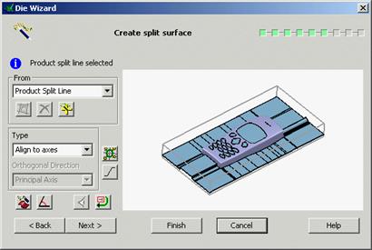
The next page allows the user to edit the created split surface. In this example the split surface is required to use a combination run off of radially and along axis.
· Select the ‘Advanced split surface options’ ![]()
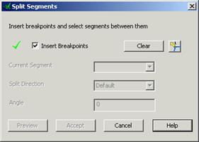
 The Split Segments form appears.
· Select clear to remove any existing segments from the curve.
· Set the corner type to run in both directions.![]()
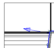
· Using the mouse create breakpoints at the positions indicated.
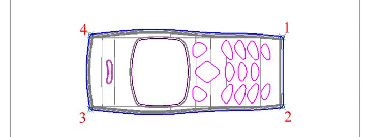
· Set the corner type to run in a single direction.![]()
· 
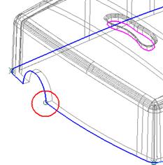 Create a single breakpoint at the
position indicated.
Create a single breakpoint at the
position indicated.
· Untick the Insert Breakpoints box to toggle the curve segments option.
 |

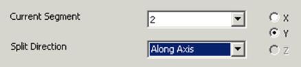
· Select segment 1 from the dropdown list and set the direction to be Along Axis.
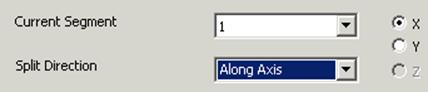
Segment 1 will indicate a split along the X-axis.
· Select segment 2 from the dropdown list and set the direction to be Along Axis.
· Repeat for segments 3 and 5.
· 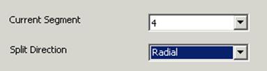 Select segment 4 from the dropdown list and
set the direction to be Radial.
Select segment 4 from the dropdown list and
set the direction to be Radial.
Segment 4 will indicate a radial split.
· Accept the form .
· Select ‘Next’ to continue.
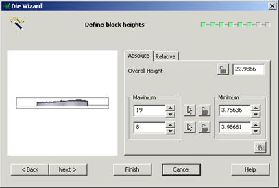
This page of the wizard allows the user to define block heights for the die inserts. Values can be determined using absolute or relative dimensions, specifying an overall height or by fixing maximum and minimum values of the upper and lower parts.
· Set a Minimum Upper value of 30.
· Set a Minimum Lower value of 25.
· Select ‘Next’ to continue.
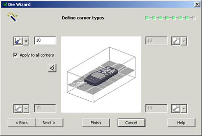
 This page of the wizard allows the user to define corner types.
There are three types of corner definition, Radial, Chamfer and none. These can
be applied either individually or globally to the insert corners.
This page of the wizard allows the user to define corner types.
There are three types of corner definition, Radial, Chamfer and none. These can
be applied either individually or globally to the insert corners.
· Set a 10mm Chamfer and tick Apply to all corners.
· Select ‘Next’ to continue.
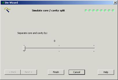
The final page of the wizard allows the user to simulate core and cavity separation.
 |
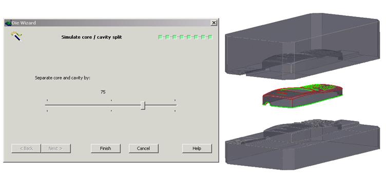
· Move the slider to simulate separation.
· Select Finish to exit and complete the wizard.
Уважаемый посетитель!
Чтобы распечатать файл, скачайте его (в формате Word).
Ссылка на скачивание - внизу страницы.