The form displays that a surface has been selected.
· Press Preview and Accept to perform the stitching.
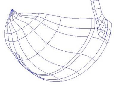

The surface has been stitched.
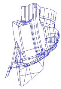
The round surface needs limiting back to the flange surface to finish off this area.
Flange surface.
· Select the two surfaces shown and Blank Except (Ctrl +K).
· Create a composite curve from the edge curve of the flange surface as shown below.
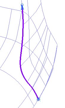
 Use
Define Start and End points on the Composite Curve dialogue to create the curve
shown.
Use
Define Start and End points on the Composite Curve dialogue to create the curve
shown.
· Select the curved surface and enter into Trim Region Editing.
·
![]() Select the Pcurves menu and the make
pcurves from projecting wireframe icon.
Select the Pcurves menu and the make
pcurves from projecting wireframe icon.
· In the form select the option Projected.
· Select the composite curve and Dismiss the form.
·
Select the Boundary menu and the Recreate
icon. ![]()
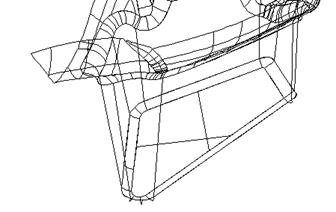
· Create a boundary around the unwanted piece to leave the result shown.
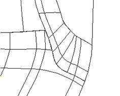
The round surface is now trimmed neatly to the flange.
Before Gap 3 is filled, a split surface needs to be generated. This is achieved by selecting the top trimmed surface and
then altering the trimming to produce a different surface.
· Unblank all of the surfaces.
· Select the top thin trimmed surface and blank all of the other surfaces (Ctrl K).
 |
· ![]() Select the thin surface and enter into Trim Region Editing.
Select the thin surface and enter into Trim Region Editing.
· Delete the boundary on the surface by selecting Explode.
· Select the Pcurve edits menu.
This pcurve needs to be broken in half and then re-trimmed to generate a split surface.
· Zoom into the area shown.


·
Select the ppoint
as shown and use Break p-curve ![]() to split at that ppoint.
to split at that ppoint.
· Select the outer pcurves and delete them.
· Create a new boundary using the remaining pcurve and rear edge of the surface to give the result shown below.
The split top surface has been generated.
· Unblank all of the surfaces and save the model as temp-piston.
Gap 3 is a large hole in the model, due to missing data, stored in another IGES file. By loading it into a New Model it can be checked before putting the data into our piston model.
· Create a new model and Import the file cyl1_1_2.igs.
· Rearrange the models using Window è Tile
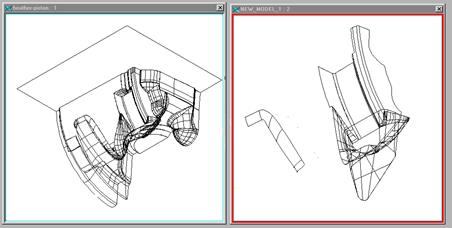
The active model will have a blue title bar. Model compare will check the primary model against the secondary and highlight the areas that are different in the Secondary model. Only these areas need to be copied into the piston model.
· With the new model active (blue title bar), select Model Compare from the Tools menu
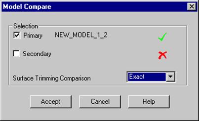
The model compare form appears. This form allows you to choose which model is the primary model and which model is the secondary model. The differences in the model are selected in the primary model.
· Click on the Secondary box, activate our original model (blue title bar) and Accept the form.
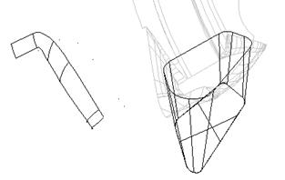
There is some wireframe data and an extruded surface that have been highlighted.
![]() Extruded surfaces
Extruded surfaces
![]()
Wireframe
·  Blank Except the selected items (Ctrl
K).
Blank Except the selected items (Ctrl
K).
· Select the wireframe only and Delete it.
· Select the extruded surfaces and select Copy.
· ![]() Select the original model and
Select paste.
Select the original model and
Select paste.
The extrusion surfaces should now be seen in the original model.
· Close the New Model to leave just the original model open – temp-piston.
· Put the new surfaces on the level 6 :core.
· Switch the level 6: core on.
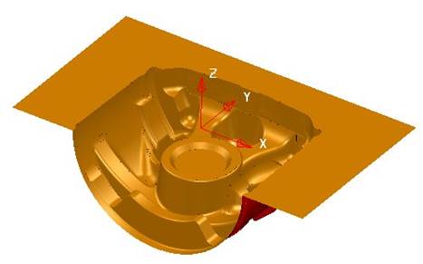
 The deep drawn pocket as shown will be filleted to the main surfaces
and the bottom edge will be filleted.
The deep drawn pocket as shown will be filleted to the main surfaces
and the bottom edge will be filleted.
· Blank except the newly copied ones and the surfaces that intersect them similar to that shown.
· Select all of the surfaces and Reverse them so that they are Blue on the outside.
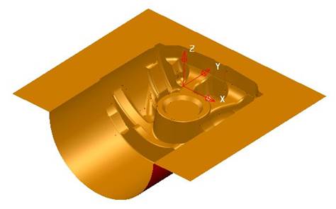
· Generate a 3mm concave fillet between the sides and the tapered box.
· Select the taper surface and the flat bottom.
· Create a 2mm convex fillet between these surfaces.
· Select all of the surfaces and Reverse so that Blue is inside.
· Move the fillet surfaces onto level 6 : core.
Now that the core half is complete we are going to create a workplane to mirror the surfaces.
· Select Unblank and create a workplane at 0.
·
 Select all
of the surfaces.
Select all
of the surfaces.
· From the Edits toolbar select Mirror.
·
Select the mirror in YZ icon. ![]()
Both sides of the model are shown. However, to complete the core, an extruded surface needs to be generated to provide a split/run off surface.

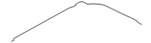
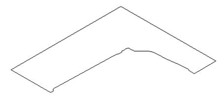
· Create a composite curve along the left edge of the model
· Create a surface of extrusion using the composite curve 90mm along the Y-axis to give the final result shown on the next page.
The model is complete.
· Save the Model.
Уважаемый посетитель!
Чтобы распечатать файл, скачайте его (в формате Word).
Ссылка на скачивание - внизу страницы.