· Select the lower plane and fillet and delete them.
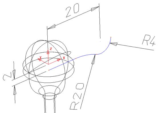
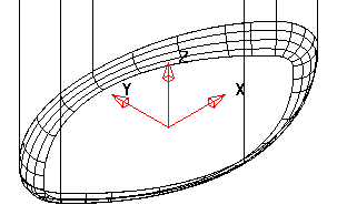
· Select the X plane and create a Plane Primitive at 0 0 20 with a width of 110 and a length of 60.
· Convert the plane to a Power Surface and change the direction if required so the blue surface is on the X+ direction as shown.
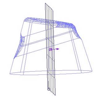

This set if selected surfaces will become the secondary set.
![]()
· Drag a box over the surfaces on the left as indicated.
· Select fillet surface. Set a radius of 2mm and Convex.
· Select the Plane surface.
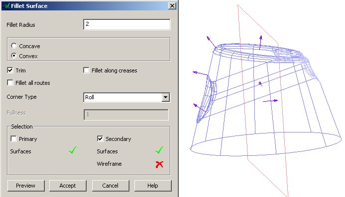
The selected surface turns pink and the secondary surface option is ticked.
· Select Accept.
· Select the first track and then select the Apply button.
· Select the last track and then select the Apply button.
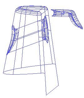

The fillets are produced and most of the other surfaces have been trimmed back.
· Delete this remaining surface.
·  Limit
the bottom of the plane back to complete the model.
Limit
the bottom of the plane back to complete the model.
Hint: create a line from the bottom ends of the cone. Limit the surface to the new wireframe.
· Select Fileè Close and then Yes.
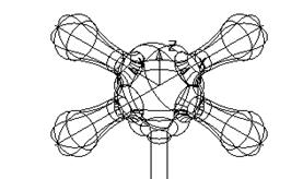
Create the following kitchen tap shape.
· Select Create New Model. ![]()
·
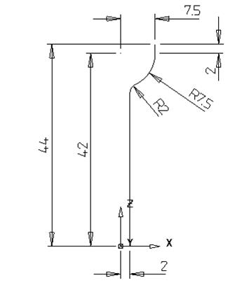 |
· Select the Z plane and create a surface of revolution from this shape.
· Create a workplane at 0 0 44
· Generate a Sphere Primitive of radius 7.5 at the new workplane.
· Select the Workplane then select limit under the Edit toolbar and then the sphere.
 |
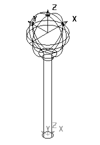
The sphere is then limited to the workplane and the top half should be kept. This will only work if the correct Principal Plane is set.
·
 |
· Create a surface of revolution around X Principal Plane.
·
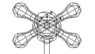 |
The four arms need to be filleted to the central section. Make sure that when shaded, all of the surfaces are blue. We do not want to fillet each arm to each other or waste time generating the route so we are going to use the Secondary surfaces option.
· Select the central section (the revolved surface and the sphere).
· 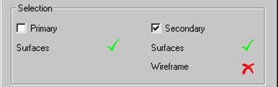 Select fillet surface and select
the four arm surfaces.
Select fillet surface and select
the four arm surfaces.
On the form the option secondary surfaces becomes ticked.
· Enter a concave radius of 2
·
 |
· Select the fillet tracks in turn and Accept to finish the model.
· Select Fileè Close and then Yes.
Variable fillets are easily created along the fillet track using the mouse to identify KEY points or using functionality within the form to position the fillet arcs either by Parametric, Relative or Absolute values.
· Select Create New Model. ![]()
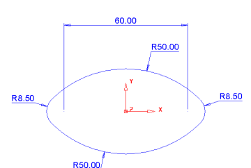
· Create a Workplane at 0.
· Create two circles with radius 8.5 at 30 and –30 in X.
· Create a Fitted arc of radius 50 either side of the two circles to form the following shape.
· Create a composite curve from the wireframe.
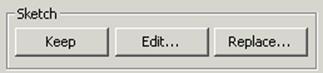
· Generate a Surface Extrusion.
· Change the Length to 60 and select the Keep button.
The composite curve is needed to create a Fill in surface at the bottom of the extrusion.
· ![]() Press Accept.
Press Accept.
· Select the composite curve and create a Fill in surface
· Reverse the surface so the red side isfacing upthe Z axis.
· ![]() Delete the
composite curve.
Delete the
composite curve.
· Select both surfaces and select the Fillet surface icon.
· Input a fillet radius of 3 select Convex and press Accept.
· Select a view down Z.
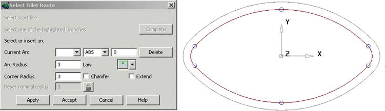
The fillet track is displayed with circles showing KEY points that can be snapped to using the mouse. By snapping at these KEY points an arc of the initial radius is created. The value of this radius can be modified in the Arc Radius area of the form.
· Snap to each of the 6 circles when the word KEY appears.
· Create 6 arcs by snapping KEY points around the fillet route starting at the right and working your way around clockwise as shown on the next page.
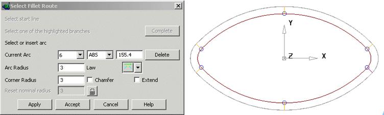
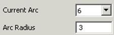
A radius appears for each point and this becomes numbered in the current arc part of the form. Individual arcs can be selected from this form or by manually clicking on them. The radius can be changed in the form or dragged manually.
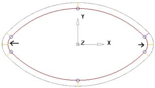
![]() New points to place radii on the fillet track can be entered by
clicking on the track or by entering a parameter position. To enter a parameter
position, select the nearest fillet and, check the number on the form in the
Current Arc box, work out the number required, change the ABS to PAR, enter the
value such as 4.5 and press Return.
New points to place radii on the fillet track can be entered by
clicking on the track or by entering a parameter position. To enter a parameter
position, select the nearest fillet and, check the number on the form in the
Current Arc box, work out the number required, change the ABS to PAR, enter the
value such as 4.5 and press Return.
· Insert two new radii between the two at each side, as shown.
The radius for these new arcs can be changed.
When there is an arc the fillet value is fixed at that point. If the next radius value ids different the radius will change along the distance.
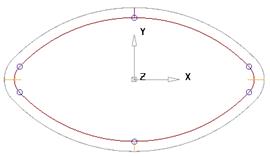
· Select the new arcs and change the radius to 5mm.
· Select the arcs (in turn) either side of the new larger arcs and select Delete off the form.
When there is an arc the fillet value is fixed at that point. If the next radius value ids different the radius will change along the distance.
· Select Apply.
The variable radius fillet has been produced.
· Select Fileè Close and then Yes.
Уважаемый посетитель!
Чтобы распечатать файл, скачайте его (в формате Word).
Ссылка на скачивание - внизу страницы.