159.253 Computer Systems
Data Communications
“You see, wire telegraph is a kind of a very, very long cat. You pull his tail in New York, and his head is meowing in Los Angeles. Do you understand this?
And radio operates in exactly the same way; you send signals here, they receive them there
The only difference is
that there is no cat”
Albert Einstein
Media
Tanenbaum 3rd edition: 82-100
TYPICAL PARAMETERS
Twisted pair (wire)
16-600Mbps
A few km
![]()
Coax
100Mbps
500m
![]()
Fibre optic cable
10Gbps
1000km
Radio
10kbps – 100Mbps
Satellite
100Mbps
Voice grade telephone
56kbps
ADSL (phone wire)
8Mbps
10km
Bit Encoding
VARIOUS TECHNOLOGIES
0
1
Voltage levels:
Inside CPU
0V
5V
(or 3.3V or 2.8V)
RS232 (V.24)
-12V
+12V
Current flow
20mA current generators
transmitter
transmitter
Bit Encoding
VARIOUS TECHNOLOGIES
0
1
Voltage levels:
Inside CPU
0V
5V
(or 3.3V or 2.8V)
RS232 (V.24)
-12V
+12V
Current flow
0mA
20mA
Direction of voltage change at clock edge
1
1
1
0
0
0
1
Bit Encoding
VARIOUS TECHNOLOGIES
0
1
Voltage levels:
Inside CPU
0V
5V
(or 3.3V or 2.8V)
RS232 (V.24)
-12V
+12V
Current flow
0mA
20mA
Direction of voltage change at clock edge
Amplitude and frequency modulation
light
dark
Light transmission
Parallel Transmission
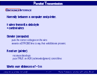
CENTRONICS INTERFACE
Normally between a computer and printer.
8 wires transmit a data byte + control wires
Sender (computer) puts the correct voltages on the wire asserts a STROBE line to say that valid data is present.
Receiver (printer)
receives data byte puts TRUE on ACK (acknowledgment) control line
Works over distances of ~ 5m
Serial Transmission
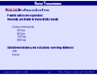
PROBLEMS WITH PARALLEL DATA PATHS
Parallel cables are expensive! Generally preferable to transmit bits serially Common local speeds: 300 bps 600 bps 1200 bps 9600 bps
Serial transmission used exclusively over long distances ATM Internet
Bit Synchronisation
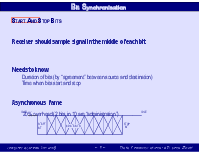
START AND STOP BITS
Receiver should sample signal in the middle of each bit
Needs to know Duration of bits (by “agreement” between source and destination) Time when bits start and stop
Asynchronous frame
20% overhead (2 bits in 10 are “administration”)
Bit Synchronisation
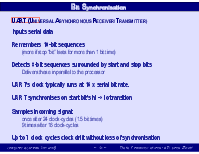
UART
(UNIVERSAL ASYNCHRONOUS RECEIVER/TRANSMITTER)
Inputs serial data
Remembers 10-bit sequences (more if stop “bit” lasts for more than 1 bit time)
Detects 8-bit sequences surrounded by start and stop bits Delivers these in parallel to the processor
UART’s clock typically runs at 16 x serial bit rate.
UART synchronises on start bit’s hi -> lo transition
Samples incoming signal: once after 24 clock-cycles (1.5 bit times) 9 times after 16 clock-cycles
Up to 7 clock cycles clock drift without loss of synchronisation
Non-Data Signals
BREAK SIGNAL
Logic 0 state > ~ 1/5 sec is interpreted as a BREAK signal. (For current loop this occurred if the wire was disconnected or broken) Length of break is not related to the transmission rate
Can be used as an auto speed detect feature - The user generates a break signal The remote system goes to a new bit rate and sends “login:” User stops sending Breaks when the correct message appears
Bit Encoding
FIBRE OPTIC TRANSMISSION
Light transmitted by total internal reflection at glass/glass boundary Glass is highly transparent for 3 IR light wavelengths: 850, 1300, 1550 nm 1 encoded as a light pulse; 0 encoded as a dark period
Speed limit > 25,000GHz for all three frequencies Actual transmission speeds (~10GHz) limited by computer switching technology
Transmitting Data over Phone Lines
MODULATION
Sine waves
Amplitude
3600
00
Phase
Wavelength (= 1/frequency)
Transmitting Data over Phone Lines
THE TELEPHONE SYSTEM
Frequency range optimised for voice signals
Direct transmission of digital data not possible Long sequences of 1's or 0's look like a signal with frequency 0Hz Frequency for 9600bps sequences of alternating 0's and 1's > 3400Hz.
Modulate an audio-frequency carrier signal with digital data Carrier always above low-f cutoff To get high data rates at <3400Hz, squeeze multiple bits into a signal element
Transmitting Data over Phone Lines
FREQUENCY MODULATION
Used for bit rates of 300bps or below.
logic 0
f = 1180Hz
010=
Note: exaggerated frequency difference in this diagram
Transmitting Data over Phone Lines
FREQUENCY MODULATION
Frequency shift keying
Simplex- transmission only in one direction Half-duplex - alternating transmission Full duplex - both sides talk at once.
Full-duplex requires another pair of frequencies logic 1 = 1650Hz logic 0 = 1850Hz
The side that started the call is in originate mode uses the first set of frequencies (980 and 1180Hz) The side that answers the call is in answer mode uses the second set of frequencies
Уважаемый посетитель!
Чтобы распечатать файл, скачайте его (в формате Word).
Ссылка на скачивание - внизу страницы.