|
In Figure 3, the loading and unloading
curves are shown for some Ti/Si and C/Si coatings. Comparing the plots 3a
and 3b, one can see that with increasing target-substrate distance, the
coating plasticity increases. It should be noted here that its nanohardness
increases as well, and rather substantially.
For the C/Si film, the scratch microphotographs at different
indentation loads are shown in Figure 4. Here, d=90 mm, and the
carbon film thickness t=0.11 mm. In spite of the
small film thickness, it flakes away from the substrate even at the minimal
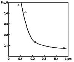
indentation load of 0.01 N. It is seen from Figure 2 that for the Ti/Si
film of the same thickness, Fcr»0.35 N. Thus, the
adhesion of Ti/Si coating is much better than that of C/Si. The reason for
that is in big internal tensions in deposited carbon films often resulting
in their spontaneous cracking as is seen in Figure 4c. Also, the presence
of big tensions is confirmed by the atypical unloading curve for the C/Si
coating, which is placed to the left of the loading curve (see Figure 3c).
Earlier, we observed significant cracking of carbon films deposited on
glass at the target-substrate distance of 50 mm.
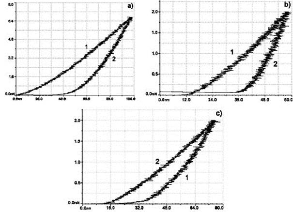 FIGURE 3. Loading (1)
and unloading (2) curves for: a) Ti/Si coating, t=0.23 mm, d=55 mm; b) Ti/Si coating, t=0.07
mm, d=90 mm; c) C/Si coating, t=0.11
mm, d=55 mm. Maximum normal force
FN=2 mN
FIGURE 3. Loading (1)
and unloading (2) curves for: a) Ti/Si coating, t=0.23 mm, d=55 mm; b) Ti/Si coating, t=0.07
mm, d=90 mm; c) C/Si coating, t=0.11
mm, d=55 mm. Maximum normal force
FN=2 mN
In Figure 5, the scratch microphotographs of Ti/Fe (t=0.08
mm) and C/Fe (t=0.13 mm) films are shown. In
spite of the Ti coating is ~1.5 times thinner than C coating, its adhesion
is evidently worse. Meanwhile, the difference in the linear expansion
coefficients of titanium and iron (8.3×10⁻⁶ and 12×10–6
K–1, respectively) is smaller than such difference for carbon
and iron (26.7×10⁻⁶ and 12×10–6 K–1), so that
internal tensions in the carbon film is higher. Obviously, in this case,
the main factor determining the adhesion of C/Fe coating is the formation
of strong chemical bond Fe-C between the film and substrate.
Comparing the adhesion of the Ti/Fe coating (Fcr=0.01
N at t=0.08 mm) and Ti/Si coating (Fcr=0.35 N at t=0.11
mm), one can see significantly better adhesion of the Ti/Si
coating. This is also connected with the formation of strong chemical bonds
in the film-substrate system due to the substrate heating by ablation
plasma. Since the compounds of titanium and silicon Ti5Si3,
TiSi, TiSi2 are formed at lower temperature (860° C) than the
compounds of titanium and iron TiFe, Ti3Fe3O
(1317 °C) [5], the probability of the formation of Ti-Si bonds is
higher.
CONCLUSION
The investigations performed have shown that the adhesion
strength of thin-film coatings substantially reduces as their thickness
increases and target-substrate distance decreases. At all other conditions
fixed, the adhesion of Ti/Si coatings is better than that of C/Si coatings
that is explained by big internal tensions in carbon films. At the same
time, the adhesion of Ti/Fe coatings is worse than that of C/Fe coatings
that can be explained by the formation of strong chemical bonds Fe-C in the
transition region between the coating and substrate.
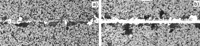 FIGURE 4. Scratch
microphotographs of C/Si film: a) FN=0.09 N; b) FN=0.43
N, t=0.111 mm, d=90
mm
FIGURE 4. Scratch
microphotographs of C/Si film: a) FN=0.09 N; b) FN=0.43
N, t=0.111 mm, d=90
mm
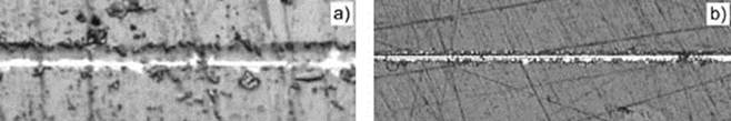 FIGURE 5. Scratch
microphotographs of Ti/Fe coating: a) FN =0.02 N, t=0.082
mm; b) FN =0.02
N, t=0.127 mm, d=90
mm
FIGURE 5. Scratch
microphotographs of Ti/Fe coating: a) FN =0.02 N, t=0.082
mm; b) FN =0.02
N, t=0.127 mm, d=90
mm
REFERENCES
1. Ivanov Yu. F., Matvienko V. M., Potyomkin A.
V., Remnev G. E., Zakutaev A. N., in Ion Solid Interactions for Materials
Modification, Processing, edited by D. B. Poker, D. Ila, Y. -S. Cheng, L.
R. Harriott, T. W. Sigman, Mater. Res. Soc. Proc., 396, Pittsburg PA , 1996, 593–598.
2. Renk T. J., Provencio P. P., Prasad S. V. et
al. Materials Modification using Intense Ion Beams // Proceedings of
the IEEE, 92, 1057–1081, 2004.
3. Xianghui Wang, Xianghuai Liu, Xi Wang et
al., Surf., Coat. Techn.
158-159, 563–567, 2002.
4. Baglin J. E. E., Nucl. Instrum., Meth. Phys.
Res. B 65, 119–128, 1992.
5. Kornilov I. N., Budberg P. B. State Diagram of Double, Triple Titanium Systems. M.: VINITI, 1961 (in Russian).
|