|
FIGURE 5. Schematic of experimental setup for NOx removal by IREB |
FIGURE 6. NOx concentration as a function of IREB shot |
|
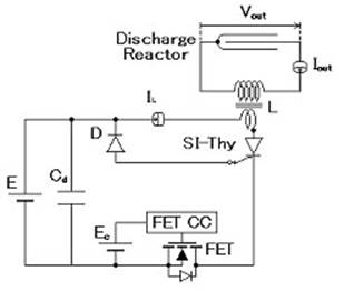
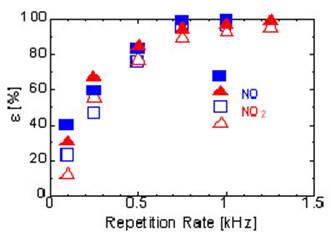
Figure 7 shows the circuit diagram of the inductive energy storage (IES) pulsed-power generator. A static induction thyristor (SI-Thyristor) is used as the main switch. The principle of the operation is as follows. First, the storage capacitor (Cd) is initially charged by DC voltage supply (E). When the field effect transistor (FET) is turned on, Cd discharges through L, SI-Thyristor and FET. Additionally, the inductive energy is stored on L. The capacitance of Cd is large enough so that its voltage does not change very much during this discharge. Second, when the current in L reaches a certain value, FET is turned off, interrupting the cathode current of SI-Thyristor. As a result, the current is forced to flow through the gate of SI-Thyristor and the diode (D). This current quickly draws the carriers out of the SI-Thyristor. Finally, in the absence of carriers, the SI-Thyristor turns off abruptly, inducing a high voltage on L. The induced voltage is further multiplied by the transformer, resulting in the breakdown in a discharge reactor of coaxial cylinder configuration. Figure 8 shows experimental results of NO and NO2 removal in nitrogen atmosphere at E=90 V, the inductive stored energy (WL) of 4.7 mJ/shot, and the initial NO and NO2 concentration of 200 ppm. In Figure 8, the vertical axis shows the NO ant NO2 removal rates (ε). It is seen from Figure 8 that the NO and NO2 removal rates increase with increasing repetition rate, approaching 100 % at the repetition rate of 750 and 1250 Hz, respectively [18]. Such results are considered to be due to a large amount of nitrogen radicals produced. CONCLUSIONS From these experimental results, we have obtained the following conclusions: · The Si nanosized powders, which have been successfully synthesized by the IBE method, indicate blue-light emission. The photoluminescence is very stable, even left for four months after the synthesis. · Using the PWD method, Ni-Fe-O nanosized powders are prepared to evaporate Ni and Fe wires in O2 ambient pressure. Sintered Ni-Fe-O nanosized powders exhibit sharp resistivity changes at the T ranging from 203 to 285 °C. · The treatment of NOx gas was carried out by irradiating IREB, and 70 % of NOx is removed by firing 10 shots of IREB. Additionally, the removal efficiency of NOx is estimated to be 20–100 g/kWh. · The experiments of NOx gas treatment was also carried out by using inductive-energy-storage (IES) pulsed power generator. As a result, NO and NO2 removal rate increases with increasing repetition rate.
|
|
FIGURE 7. Circuit diagram of the IES generator |
FIGURE 8. Experimental results of NO and NO2 removal rate in nitrogen atmosphere at E=90V |
|
ACKNOWLEDGEMENTS This work was supported in part by the Ministry of Education, Culture, Sports, Science, and Technology of Japan under a Grant-in-Aid for the Scientific Research. This work was also partly supported by the 21st COE Program. Enthusiastic support and assistance throughout these studies were given by many students as well as technicians of EDI, Nagaoka University of Technology. REFERENCES 1. Shimotori Y. et al., J. Appl. Phys., 63, 968, 1988. 2. Yatsui K. Laser Part. Beams, 7, 733, 1989. 3. Yatsui K. et al., Phys. Plasmas, 1, 1730, 1994. 4. Sonegawa T., et al., Jpn. J. Appl. Phys., 68, 2193, 1996. 5. Yatsui K., Grigoriu C., Masugata K., Jiang W., Sonegawa T., Jpn. J. Appl. Phys., 36, 4928, 1997. 6. Sonegawa T., Yatsui K., J. Mater. Sci. Letters, 17, 1685, 1998. 7. Yatsui K., Sonegawa T., Ohotomo K., Jiang W., Mater. Chem. Phys., 54, 219, 1998. 8. Sonegawa T., Ohotomo K., Jiang W., Yatsui K., IEEE Trans. Plasma Sci., 28, 1545, 2000. 9. Sonegawa T., Arakaki T., Maehara T., Jiang W., K. Yatsui, Jpn. J. Appl. Phys., 40, 1049, 2001. 10. Kitajima K., Suzuki T., Jiang W., Yatsui K., Jpn. J. Appl. Phys., 40, 1030, 2001. 11. Suematsu H. et al., Appl. Phys. Letters, 80, 1153, 2002. 12. Suematsu H. et al., Thin Solid Films, 407, 132, 2002. 13. Suematsu H., Sengiku M., Kato K., Jiang W., Yatsui K., Thin Solid Films, 407, 136, 2002. 14. Suematsu H. et al., J. Mater. Res., 19, 1011, 2004. 15. Yatsui K., Gunji M., Yang S. C., Suematsu H., Jiang W., in preparation. 16. Ikegaki T. et al., Jpn. J. Appl. Phys., 40, 1104, 2001. 17. Imada G., Yatsui K., IEEE Trans. Plasma Sci., 31, 295, 2003. 18. Endo F., Jiang W., Yatsui K., Shimizu N., IEEJ Trans. FM, 124, 321, 2004. 19. Jiang W., Shimada N., Prasada S. D., Yatsui K., IEEE Trans. PI. Sci., 32, 54, 2004. 20. Yatsui K., Yumino N., Masugata K. Laser Interaction, Related Plasma Phenomena, edited by H. Hora, G. H. Miley. New York, Plenum, 1992, 567. |
Уважаемый посетитель!
Чтобы распечатать файл, скачайте его (в формате Word).
Ссылка на скачивание - внизу страницы.