Contents
6 Expansion and Upgrade 6-1
6.1 Equipment Expansion and Upgrade 6-1
6.1.1 Tributary Expansion and Upgrade 6-1
6.1.2 Ethernet Service Expansion and Upgrade 6-3
6.1.3 ATM Service Expansion and Upgrade 6-4
6.1.4 Line Rate Expansion and Upgrade 6-5
6.1.5 Cross-Connect Capacity Expansion and Upgrade 6-8
6.1.6 Add an Extended Subrack 6-11
6.2 Network Expansion and Upgrade 6-13
6.2.1 In-Service Adding an NE 6-13
Figures
Figure 6-1 NE3 tributary board expansion 6-2
Figure 6-2 Ethernet service expansion (NE3) 6-3
Figure 6-3 Ethernet service expansion (NE5) 6-3
Figure 6-4 ATM service expansion and upgrade in NE1 6-5
Figure 6-5 Board configuration for line expansion of NE2 (mode 1) 6-6
Figure 6-6 Board configuration for line expansion of NE1 (mode 2) 6-7
Figure 6-7 Slot access capacity with GXCS 6-9
Figure 6-8 Slot access capacity with EXCS 6-10
Figure 6-9 Typical configuration of the extended subrack in NE1 6-11
Figure 6-10 Add a node to a two-fiber bidirectional MSP ring 6-13
Figure 6-11 The two-fiber bidirectional MSP ring with NE6 added 6-14
Tables
Table 6-1 Two modes for line expansion 6-6
Table 6-2 Comparison among GXCS, EXCS and UXCS 6-8
This chapter introduces the expansion and upgrade of the OptiX OSN 3500 in two parts:
n Equipment expansion and upgrade
n Network expansion and upgrade
The equipment expansion and upgrade means to add boards and upgrade software to meet the requirement of services.
It is a shortcut to meet the requirement of increasing services and to maximize the utilization of operator’s investment.
The equipment to be expanded and upgraded should be configured based on the increasing service, transmission distance and other requirements. The OptiX OSN 3500 can be configured as MADM, so during the expansion and upgrade, the board should be added first and then the subrack.
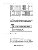
Expansion can be achieved by adding interface boards, tributary boards or replacing tributary boards of larger capacity. When adding or replacing boards, note to add or replace the corresponding interface boards and add cables, cable ties and labels. For the slot configuration of tributary boards and interface boards, as well as their relationship, refer to section A.2.4 “PDH Board”.
The boards that need to add/drop services through interface board should be inserted in slots 2–5 or slots 13–16.
If the processing slot holds PQ1/PQM, the service can be added/dropped through the corresponding two interface boards. If the processing slot holds PD3/SEP1/EFS0, the service can be added/dropped through one interface board, which should be inserted in the leading-out slot of smaller number. Otherwise, the service fails. Likewise, the bridging unit TSB4/TSB8 used for TPS should be inserted in the first slot of slots corresponding to protection processing board.
The OptiX OSN 3500 provides three protection groups at the same time, to support the TPS protection to three kinds of service in a subrack. For the TPS configuration of each kind of service, refer to section A.3.1 “Equipment-Level Protection Configuration Requirement”.
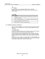
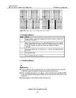
Expand the tributary board of NE3 and provide TPS, as shown in Figure 6-1. The expansion board PQ1 is in slot 4, its two interface boards D75S are in slot 21 and slot 22 respectively, the protection PQ1 is in slot 1 to provide TPS for E1 services of slot 2 and slot 3.
Figure 6-1 NE3 tributary board expansion
![]() Caution:
Caution:
The system reserves slots for processing boards and corresponding interface boards.
The processing board should match with the interface board.
The system is capable of lower order cross-connect processing.
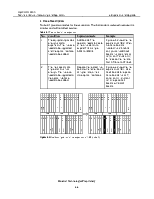
|
Step |
Action |
|
1 |
Check the working status of the expansion board and check whether the software is compliant. |
|
2 |
Install related hardware, such as inserting boards and cabling. |
|
3 |
Configure the TPS protection group through NM or add the tributary board to this protection group. |
|
4 |
Configure services on the tributary board. |
Уважаемый посетитель!
Чтобы распечатать файл, скачайте его (в формате Word).
Ссылка на скачивание - внизу страницы.