Contents
A Multiplexing Structure, Frame Structure and Overhead Byte A-1
A.1 SDH A-1
A.2 Multiplexing Structure A-2
A.3 Frame Structure A-3
A.4 SOH A-4
A.4.1 STM-1 SOH A-4
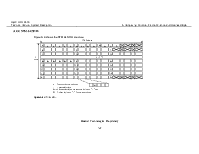
A.4.2 STM-4 SOH A-5
A.4.3 STM-16 SOH A-6
A.4.4 STM-64 SOH A-7
A.4.5 SOH Bytes A-8
A.5 POH Bytes A-9
A.5.1 VC-3/VC-4/VC-4-xc Higher Order POH Bytes A-9
A.5.2 VC-12 Lower Order POH Bytes A-9
Figures
Figure A-1 Multiplexing structure A-2
Figure A-2 SDH frame structure A-3
Figure A-3 STM-1 SOH A-4
Figure A-4 STM-4 SOH A-5
Figure A-5 STM-16 SOH A-6
Figure A-6 STM-64 SOH A-7
Tables
Table A-1 SDH transmission rate level A-1
Table A-2 SOH byte A-8
Table A-3 VC-3/VC-4/VC-4-xc higher order POH bytes A-9
Table A-4 VC-12 lower order POH bytes A-9
This appendix covers the processing of the synchronous digital hierarchy (SDH), multiplexing structure, frame structure and overhead byte that are applicable to the OptiX OSN 9500.
A.1 SDH
The first rate level of SDH signal is 155520 kbit/s, and signals at higher rate levels can be formed by byte interleaving and multiplexing in the proportion of N (N=4, 16, 64…). See Table A-1.
Table A-1 SDH transmission rate level
|
SDH |
Bit rate (kbit/s) |
|
STM-1 |
155520 |
|
STM-4 |
622080 |
|
STM-16 |
2488320 |
|
STM-64 |
9953280 |
A.2 Multiplexing Structure
Multiplexing and multiplexing structure of various services on the OptiX OSN 9500 are shown in Figure A-1.
Figure A-1 Multiplexing structure
A.3 Frame Structure
Figure A-2 shows the SDH frame structure.
Figure A-2 SDH frame structure
A.4 SOH
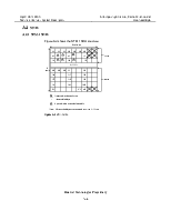
A.4.1 STM-1 SOH
Figure A-3 shows the STM-1 SOH structure.
Figure A-3 STM-1 SOH
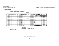
A.4.2 STM-4 SOH
Figure A-4 shows the STM-4 SOH structure.
Figure A-4 STM-4 SOH
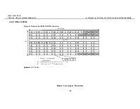
A.4.3 STM-16 SOH
Figure A-5 shows the STM-16 SOH structure.
Figure A-5 STM-16 SOH
A.4.4 STM-64 SOH
Figure A-6 shows the STM-64 SOH structure.
Figure A-6 STM-64 SOH
A.4.5 SOH Bytes
Table A-2 SOH byte
|
Byte |
Description |
|
A1 and A2 |
Framing byte. A1 = F6H, A2 = 28H |
|
B1 |
Regenerator section (RS) bit error monitoring byte BIP-8 |
|
B2 |
MS bit error monitoring byte BIP-24 x N |
|
D1, D2 and D3 |
RS DCC, 192 kbit/s |
|
D4–D12 |
MS DCC, 576 kbit/s |
|
E1 |
RS orderwire communication byte, 64 kbit/s |
|
E2 |
MS orderwire communication byte, 64 kbit/s |
|
F1 |
Data/speech channel of network provider |
|
H1 and H2 |
Administrative unit pointer |
|
H3 |
Negative pointer justification byte |
|
J0 |
RS trace byte |
|
K1 and K2 |
MS automatic protection switching (APS) byte |
|
M1 |
MS remote error indication byte |
|
S1 |
Synchronization status byte (b5–b8) |
|
Others |
Defined in future use |
A.5 POH Bytes
A.5.1 VC-3/VC-4/VC-4-xc Higher Order POH Bytes
Table A-3 VC-3/VC-4/VC-4-xc higher order POH bytes
|
J1 |
Higher order path trace byte |
|
B3 |
Higher order bit error monitoring byte BIP-8 |
|
C2 |
Higher order path signal label byte |
|
G1 |
Path status byte |
|
F2 |
Higher order user path byte |
|
H4 |
Multiframe position indication byte |
|
F3 |
Higher order user path byte |
|
K3 |
APS byte |
|
N1 |
Network operator byte |
Note: VC-4 POH locates at the first column of the VC-4 structure at Column 261, Row 9.
VC-4-xc POH locates at the first column of VC-4-xc (concatenated by X x VC-4s) at Column 261*X, Row 9.
A.5.2 VC-12 Lower Order POH Bytes
Table A-4 VC-12 lower order POH bytes
|
V5 |
Lower order path bit error, signal identifier and path status |
|
J2 |
Lower order path trace byte |
|
N2 |
Network operator byte |
|
K4 |
APS byte and Lower order remote defect indication |
Уважаемый посетитель!
Чтобы распечатать файл, скачайте его (в формате Word).
Ссылка на скачивание - внизу страницы.