The ring network composed of the OptiX OSN 3500 has the following protection modes:
n Two-Fiber bidirectional multiplex section protection ring
n Four-Fiber bidirectional multiplex section protection ring
n Sub-Network connection protection (SNCP)
Table 2-4 shows the features and applications of these protection modes.
Table 2-4 Comparison of the two protection modes
|
Protection mode Item |
Two-Fiber bidirectional MSP ring |
SNCP |
|
Maximum service capacity (K is the number of nodes) |
STM-N x K/2 |
STM-N |
|
Node cost |
Medium |
Low |
|
APS protocol |
Required |
Not required |
|
Networking flexibility |
Rather strong |
Strong |
|
System complexity |
Complicated |
Simple |
|
Switching speed |
Fast |
Fast |
This protection mode is applicable when the service is distributed. If the service is only transmitted between adjacent nodes, the service capacity can reach STM-N x K/2 (K is the number of nodes) at most in the ring. However, it is a complicated protection mechanism, requiring the support of automatic protection switching (APS) protocol and high-level network maintenance.
n Configuration plan
As shown in Figure 2-8, a ring network is composed of four NEs: A, B, C, and D, with the line rate of STM-16.
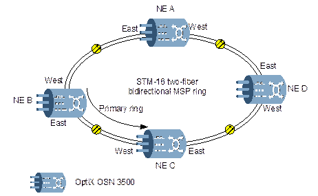
Figure 2-8 Typical ring network
Table 2-5 shows the service allocation between adjacent NEs.
Table 2-5 Service allocation of NEs
|
NE |
A |
B |
C |
D |
|
A |
- |
63 x E1 |
63 x E1 |
63 x E1 |
|
B |
63 x E1 |
- |
63 x E1 |
- |
|
C |
63 x E1 |
63 x E1 |
- |
32 x E1 |
|
D |
63 x E1 |
- |
32 x E1 |
- |
The service in a ring network is distributed and there are services to be added/dropped between adjacent nodes. Moreover, if we take the service capacity and source utilization into consideration, the two-fiber bidirectional MSP is preferable.
n Configuration description
& Note:
In a bidirectional MSP ring, generally, the service can only be configured in the first half of VC-4s; the rest is used as the protection channels. For example, channels from the ninth to sixteenth VC-4 of an STM-16 ring are generally used as protection channels. If these channels are configured to carry extra services, extra services cannot be protected.
The service on the two-fiber bidirectional MSP ring tends to be transmitted over the “uniform route”, so the bidirectional service should be configured for each direction. For services that are not added/dropped at this station, configure them as bidirectional pass-through services.
Take the service between NE A and NE C as an example, the 63 x E1 service occupies #1 VC-4 in the line, and the normal service flow is: NE A tributary unit®NE A east line unit®fiber line®NE B west line unit®NE B east line unit®NE C west line unit®NE C tributary unit, as shown in Figure 2-9.

Figure 2-9 Service flow between NE A and NE C (normal)
If the fiber between A and B breaks, the 63 x E1 services between A and C will be switched to #9 VC-4. The service flow from A to C is: NE A tributary unit®NE A west line unit (#9 VC-4)®NE D east line unit (#9 VC-4)®NE D west line unit (#9 VC-4)®NE C east line unit (#9 VC-4) ®NE C west line unit (#9 VC-4) ®NE B east line unit (#9 VC-4) ®NE B east line unit (#1 VC-4) ®NE C west line unit (#1 VC-4)®NE C tributary unit, as shown in Figure 2-10. The service from C to A is the same over the other fiber.
Уважаемый посетитель!
Чтобы распечатать файл, скачайте его (в формате Word).
Ссылка на скачивание - внизу страницы.