Contents
3 Power Distribution Unit 3-1
3.1 Power Distribution Scheme 3-1
3.2 Specifications 3-3
Figures
Figure 3-1 The power distribution unit 3-2
Figure 3-2 Front view of the power distribution unit 3-2
Tables
Table 3-1 Power distribution scheme 3-3
Table 3-2 Technical specifications for the power distribution unit 3-4
This chapter introduces the power distribution scheme and technical specifications of the OptiX OSN 9500.
The power distribution unit is installed on the top of the rear posts of the OptiX OSN 9500 cabinet. The OptiX OSN 9500 uses the power interface board (JPIU) for power supply and power protection. The power distribution unit is only responsible for accessing and distributing the power supply.
& Note:
The power distribution unit of the OptiX OSN 9500 is slightly different from that of the other OptiX equipments in function and installation position. The filter and over/under-voltage protection functions of power distribution unit are integrated on the JPIU board.
3.1 Power Distribution Scheme
As the JPIU of the OptiX OSN 9500 equipment is seated in the rear frame of the subrack, the power distribution unit is installed on the mount of the rear posts of the cabinet.
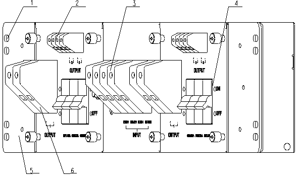
Figure 3-1 shows the overall appearance of the power distribution unit.
|
1. Mounting hole |
2. 20 A power output terminal |
3. Power input terminal |
|
4. Power switch |
5. Mounting ear |
6. 63 A power output terminal |
Figure 3-1 The power distribution unit
The power distribution unit can have two independent external power inputs, two 20 A power outputs, one 63 A power output, and power switch control.
Figure 3-2 shows a front view of the power distribution unit.

|
1. 63 A power output |
2. 20 A power output |
3. PGND |
|
4. External power input |
5. 63 A power switch |
6. 20 A power switch |
Figure 3-2 Front view of the power distribution unit
Table 3-1 shows the power distribution schemes for the power distribution unit.
Table 3-1 Power distribution scheme
|
Input/output |
Group No. |
Power supply |
Ground cable |
Remarks |
|
Power input group |
Group 1 |
NEG1 (-) |
RTN1 (+) |
External power supply 1 |
|
Group 2 |
NEG2 (-) |
RTN2 (+) |
External power supply 2 |
|
|
Power output group |
63 A power supply group |
1 (-) |
1 (+) |
Two power outputs: provide the subrack with 1+1 hot backup of 63 A power. |
|
20 A power supply group |
2 (-) |
2 (+) |
Two power outputs: provide the subrack with 1+1 hot backup of 20 A power. |
|
|
3 (-) |
3 (+) |
Two power outputs: provide the subrack with 1+1 hot backup of 20 A power. |
||
|
Protection ground |
Connected to the user protection ground. |
3.2 Specifications
Table 3-2 Technical specifications for the power distribution unit
|
Items |
Description |
|
Size |
530 mm (W) x 125 mm (D) x 132 mm (H) |
|
Weight |
About 2 kg |
|
Input voltage |
–48 V/–60 V DC |
|
Output voltage |
–48 V/–60 V DC |
Уважаемый посетитель!
Чтобы распечатать файл, скачайте его (в формате Word).
Ссылка на скачивание - внизу страницы.