Contents
5 Fixing Cabinet 5-1
5.1 Combining Cabinets 5-2
5.1.1 Procedure 5-2
5.1.2 Installation Check 5-3
5.2 Fixing Cabinets on an Overhead Cabling Frame 5-5
5.2.1 Fixing Cabinet on a Cabling Frame with a Side Trough (H £ 200 mm) 5-7
5.2.2 Fixing Cabinet on a Cabling Frame with a Side Trough (H > 200 mm) 5-8
5.2.3 Fixing Cabinet on a Cabling Frame without a Side Trough (H £ 200 mm) 5-9
5.2.4 Fixing Cabinet on a Cabling Frame without a Side Trough (H > 200 mm) 5-10
5.2.5 Installation Check 5-11
5.3 Installation Check Points 5-12
Figures
Figure 5-1 Bolt assembly 5-2
Figure 5-2 Combining cabinets 5-3
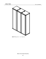
Figure 5-3 Expected result of combined cabinets 5-4
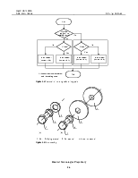
Figure 5-4 Flow chart of installing cabinet fixing parts 5-6
Figure 5-5 Bolt assembly’ 5-6
Figure 5-6 Install the cabinet on a cabling frame with a side trough (H £ 200 mm) 5-7
Figure 5-7 Fix the cabinet on a cabling frame with a side trough (H >200 mm) 5-9
Figure 5-8 Fix the cabinet on a cabling frame without a side trough ( H£200 mm) 5-10
Figure 5-9 Fix the cabinet on a cabling frame without a side trough ( H >200 mm) 5-11
Tables
Table 5-1 The contents of Chapter 5 5-1
|
Overview |
This chapter introduces the procedures and precautions for fixing the installed cabinets. To make the installed cabinets stable, the installation personnel shall fix them by combining them or by using shockproof components according to the actual situation of the equipment room. |
|
Contents |
Table 5-1 shows the contents of this chapter. |
Table 5-1 The contents of Chapter 5
|
Title |
Content |
|
5.1 Combining Cabinets |
Introduces the relevant operations and procedures for fixing cabinets by combining cabinets. |
|
5.2 Fixing Cabinets on an Overhead Cabling Frame |
Introduces the relevant operations and procedures for fixing the cabinet by installing shockproof components. |
|
5.3 Installation Check Points |
Checks the fixed cabinet to see whether the next step installation can be conducted. |
5.1 Combining Cabinets
|
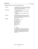
Overview |
This section introduces the procedure and precautions for combining the ETSI 600 mm cabinets. This intends to combine together the cabinets that are close to each other, so that they can become more reliable. |
|
Prerequisites |
n Cabinet installation is completed, and in compliance with the check standards. n Installation materials for combining cabinets are complete. |
|
Materials |
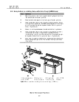
n Joint plate, as shown in Figure 5-2. n M8 x 20 bolt set, as shown in Figure 5-1.
The flat washer and spring washer must be used when assembling a bolt, as shown in Figure 5-1. |
|
1. Bolt |
2. Spring washer |
3. Flat washer |
Figure 5-1 Bolt assembly
5.1.1 Procedure
Уважаемый посетитель!
Чтобы распечатать файл, скачайте его (в формате Word).
Ссылка на скачивание - внизу страницы.