· Select File and then Import.
· Select ‘Split_surf_example.dgk ’ from PowerSHAPE_data/psmodels_n_dgk.
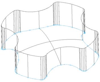
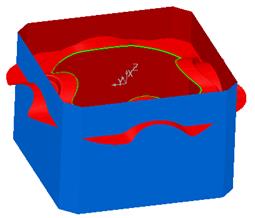
The file contains a surface model and a predefined Composite Curve, which will be used to generate the split surface.
·
Quick Select all
surfaces ![]() and
Blank (Ctrl J).
and
Blank (Ctrl J).
· With the composite curve selected, select the split surface
icon. ![]()
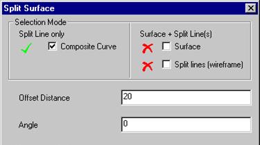
The composite curve box is ticked and selected.
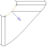
· Enter an offset distance of 50 and set the blue arrow pointing out.
· Set the split direction to Radially Out and press Preview.
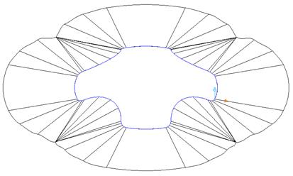
This surface is congested around the corners due to the inner corners and the offset length. A way of improving this is to use the Align to Axis option, which will align the split surface to the X or Y-axis.
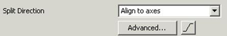
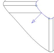
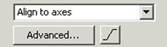
· Set the ‘split direction’ option as ‘Align to axes’ and press Preview.
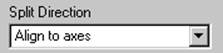
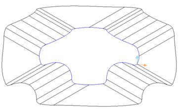
The split surface is now aligned to the axis and has reduced the way it previously curled in on itself. Further improvements can be made to the surface by using a combination of radially out and aligned to axis
· Select the Advanced option from the form.
 |
The Split Segments form appears.
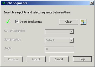
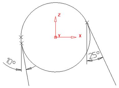
![]() Defining segments for the curve and specifying split direction for
each segment can modify Split direction.
Defining segments for the curve and specifying split direction for
each segment can modify Split direction.
· Select clear to remove any existing segments from the curve.
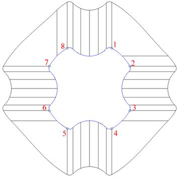
· Using the mouse click at breakpoints at the positions indicated.
· Untick the Insert Breakpoints box to toggle the curve segments option.
 |

· Select segment 1 from the dropdown list and set the direction to radial.

Segment 1 will indicate a radial split.
· Select segment 3 from the dropdown list and set the direction to radial.
Segment 3 will indicate a radial split.
· Repeat the process for segments 5 and 7
· Select Accept to close the form.
· Select Preview from the split surface form.
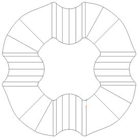
The Preview indicates a combination of radial and align to axis.
Do NOT cancel the form
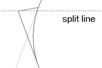
Stepped split surfaces are used to reduce the amount of bench work needed to ensure correct matching of the two mould halves. Split surfaces can be defined with: 1. A ‘land’ distance, which is the length from the outer edge of the part to the ‘step’
2. An angle for the step itself.
3. An overall length for the split surface.
In addition the user may specify different radii from the joins between the various segments, or use chamfers.
· ![]() Select the Stepped
Split Surface.
Select the Stepped
Split Surface. ![]()
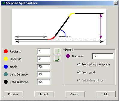
The form allows values to be defined for the stepped split.
· Enter the values as shown and Accept the form.
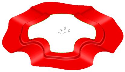
The Split Surface is produced with the defined step. A block will be created and trimmed back to the split surface.
· Create a Rectangle from X – 60 Y 60 Z -60 of width 120 and length –120.
· Select Toolsè Options, Object and then Lines.
Chamfers are created from the values set in the option form. They can be edited individually but if you have a lot of chamfers to do, then it is easier to change the default setting.
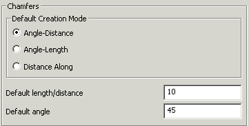
· Set the Chamfer Distance to 10.
· Press Accept.
· Create a 10mm chamfer (from line menu) on all four corners.
![]()
· Generate a composite curve.
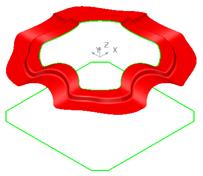
The curve will be used to generate the side walls of the block.
· Select the lower composite curve and create a Fill-in surface.
· Select the composite curve and create a surface of Extrusion with a Length of 80.
The sidewalls need to be trimmed back to the split surface.
· Limit the side walls to the split surface. Select Unblank (Ctrl L).
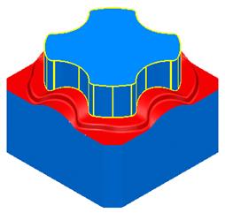
The die block is complete.
Generating a split surface does not automatically trim the model. An option has been included in PowerSHAPE, (developed as part of PS MoldMaker, which is available as a standard function) called Die Wizard. Using the active solid Die Wizard will automatically split and trim the model creating cavity and core inserts. This will be covered later on in the course.
· Select Fileè Close and then Yes.
A draft surface can be generated from either a composite curve or a set of surfaces. The draft surfaces are either projected onto the XY plane of the current workplane, or onto another pre-selected surface.
The draft surface is generated tangentially from the original surface dependent upon the angle selected, as with the Draft curve command.
Уважаемый посетитель!
Чтобы распечатать файл, скачайте его (в формате Word).
Ссылка на скачивание - внизу страницы.