Parameter curves (p-curves) are defined along points (ppoints) that lie on a surface. They are created automatically, by default during surface limiting or filleting. They can also be generated manually by projection of wireframe entities onto a surface. As moves between ppoints are linear, any curvature is controlled by the proximity of adjacent ppoints within the tolerance setting.
Boundaries are generated along the pcurve network to define trimmed areas on a surface.
Individual pcurves and boundaries are unique to a Surface and can only be accessed by opening the Trim Region Editing, toolbar (Right click on a surface for menu options or alternatively access directly from the Surface Edits toolbar).
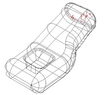
· Import the model m0_switch_housing.psmodel from Powershape_data.
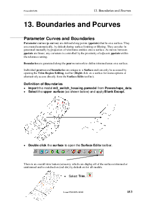
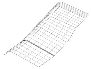
· Select the upper surface(as shown below) and apply Blank Except.
![]()
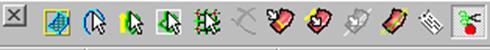
· Double click the surface to open the Surface Edits toolbar.
![]()
There is an overall trim button (scissors), which can display all of the surfaces trimmed or untrimmed and is switched on (red dot) by default on for all models.
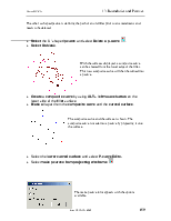
· Select Trim. ![]()
![]() The
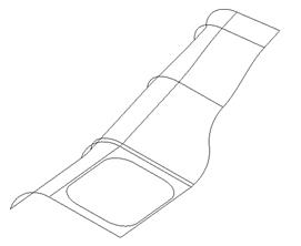
surface is now displayed without trimming. It is possible on occasions for an imported
surface to enter the model with the trimming switched off making it appear that
information is missing. If this is the case, switching the icon will correctly
display the trimmed surface.
The
surface is now displayed without trimming. It is possible on occasions for an imported
surface to enter the model with the trimming switched off making it appear that
information is missing. If this is the case, switching the icon will correctly
display the trimmed surface.
· Click Trim again to switch the trimming back on (red dot). ![]()
· From the Surface Edits toolbar, select the Trim region
editing ![]()
The Trim Region Editing toolbar appears. This has two modes, Boundary Edits and Pcurve Edits.
· ![]() Select Boundary
Edits.
Select Boundary
Edits.
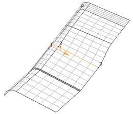
The whole surface is displayed with the trimmed area identifiable by a mesh of grey detail lines. All existing boundaries are displayed marking the edge of the surface area that is trimmed. The pcurves are not displayed in this mode.
If a boundary is deleted from a surface the associated pcurves remain but are no longer involved in the trimming process.
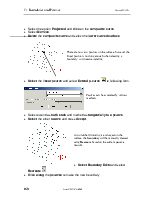
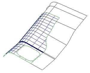
· Select Pcurve Edits.
![]()
 The
pcurves are shown along with trimmed areas. The actual Boundaries
are not displayed in this mode.
The
pcurves are shown along with trimmed areas. The actual Boundaries
are not displayed in this mode.
If a pcurve is deleted from a surface any associated boundary will also be removed.
Note: not all routes defined by pcurves are necessarily included in the boundary definition.
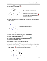
· Select Boundary Edits and click the Boundary Selector icon.
![]()
![]()
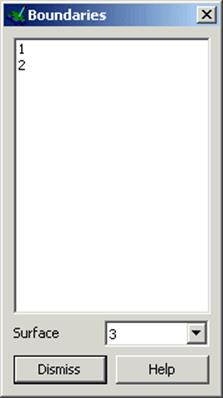
If a boundary is selected it will change colour.
The boundaries used to define the trimming of the selected surface are listed here. A boundary can be selected by highlighting it's number. Several boundaries can be multi-selected by holding down the shift key.
The use of the Crtl key will enable listed boundaries to be individually selected or deselected.
A boundary can also be directly selected from within the graphics area with a left mouse click.
Note: Trimming will only occur if a boundary forms a closed loop.
· Select both boundaries by selecting with the shift key depressed.
![]()
· Dismiss theaboveformandselectthe Explode icon.
With the boundaries deleted the trimming is removed, exposing the full surface area. The pcurves remain intact but are simply no longer in use as part of a boundary definition.
The pcurves still exist and can be made visible by toggling into Pcurve Edits.
· Select Autocreate ![]() and observe the partially trimmed model
to appear as shown below.
and observe the partially trimmed model
to appear as shown below.
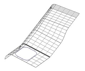
Part of the required boundary has failed to appear. This is due to there being a branch point along the network of pcurves making it impossible for the software to determine which route to take.
The easiest way to create the required trim option is to manually define the route around the pcurve network as shown in the next section.
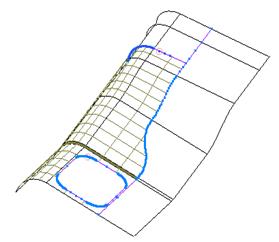
· Select Recreate ![]() to open the following form and display
all unused pcurves on the surface.
to open the following form and display
all unused pcurves on the surface.
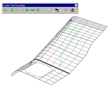
The create trim boundary toolbar appears and this is used to trace along the pcurves to define a boundary. It is similar to the composite curve toolbar.
![]() All
of the pcurves are drawn on the surface so they can be selected. To make a
boundary the pcurve track needs to be closed and you can trace along the edge
of a surface or a curve to achieve this.
All
of the pcurves are drawn on the surface so they can be selected. To make a
boundary the pcurve track needs to be closed and you can trace along the edge
of a surface or a curve to achieve this.
· Select the first pcurve and follow around to produce a closed shape.
Уважаемый посетитель!
Чтобы распечатать файл, скачайте его (в формате Word).
Ссылка на скачивание - внизу страницы.