When surfaces are limited together PowerSHAPE automatically trims back the surfaces. If it trims back the surfaces in the wrong place you can use the next solution option to go through the options to find the required solution.
When a surface is limited back a boundary is generated and only the part of the surface inside that boundary is displayed. Several surfaces can be limited with a single cutter surface.
· Select Create New Model. ![]()
· Create a workplane at 0.
· Create a plane primitive surface at the workplane of size X 50, Y 50.
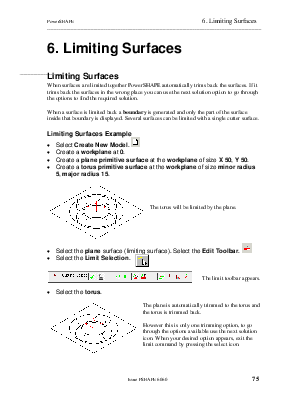
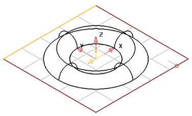
· Create a torus primitive surface at the workplane of size minor radius 5, major radius 15.
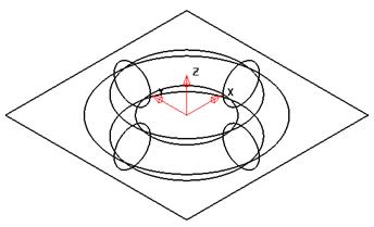
The torus will be limited by the plane.
· Select the plane surface (limiting surface). Select the Edit
Toolbar. ![]()
· ![]() Select the Limit Selection.
Select the Limit Selection.
![]()
The limit toolbar appears.
· Select the torus.
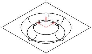
The plane is automatically trimmed to the torus and the torus is trimmed back.
However this is only one trimming option, to go through the options available use the next solution icon. When your desired option appears, exit the limit command by pressing the select icon.
![]()
· Select Next Solution.
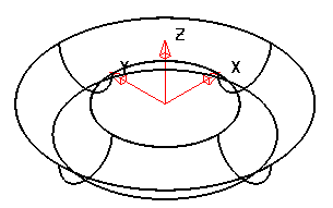
This solution shows the plane limited to a small circle, with the same lower half of the torus.
· ![]() Select Next Solution.
Select Next Solution.
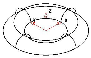
This solution shows the plane limited to a small circle, with the top part of the torus.
![]()
· Select Next Solution twice.
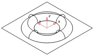 This
solution shows the plane with a circular ring limited out and the top part of
the torus.
This
solution shows the plane with a circular ring limited out and the top part of
the torus.
In between pressing the Next solution icon you can rotate and shade the model to see what option you have been given.
You can cycle through the options using next solution until you see the required one.
· Press Select. ![]()
When a single surface is selected, then the inter curve grids are shown.
· Select Undo. ![]()
· Select the plane as the cutting object and then the limit
icon ![]() .
.
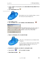
· Select keep both and change to both option.
![]()
![]()
![]()
This single side icon now changes into the ‘keep both’ icon.
When the keep both icon shows both halves it saves the top and bottom part of the surface it has limited back. This is a useful command to use when you need to keep both halves of a surface for the cavity and the die.
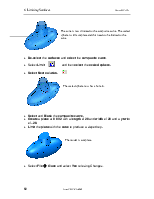
· Select the torus.
· Press Select. ![]()
· Select the top surface
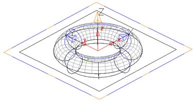
The torus has now been split into two separate surfaces, with the plane remaining as one limited surface.
A simple copy of the plane can be produced using copy and paste if an additional one was required.
· Select and delete all surfaces.
This example shows how multiple surfaces can be limited by a single surface.
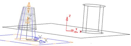
· Create a plane primitive surface at the workplane of size X 75, Y 50.
· Create a cylinder at 25 15 -10 with a radius of 5 and a length of 20.
· Create a cone at -25 -15 -10 with a base radius of 5, top radius of 2.5 and a length of 20.
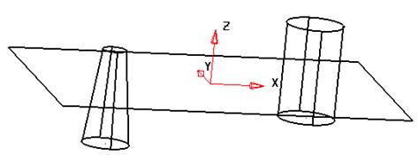
By rotating the model, the plane intersects both surfaces.
![]()
· Select the plane and then Limit Selection.
· Pick the cylinder and cone only using the cursor to make a box.
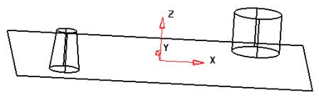
All of the three surfaces are trimmed together.
Selecting the Next Solution icon will only work on the group. To change the trimming of a single surface, select the surface and use the trimming options.
· Press Select. ![]()
· Select only the cone
When a surface is limited a boundary is generated. Part of the surface inside the boundary is displayed. Boundaries are edited in the Trim Region Editor.
Уважаемый посетитель!
Чтобы распечатать файл, скачайте его (в формате Word).
Ссылка на скачивание - внизу страницы.