BOARD TEST ROUTINE
Equipment required:
• Test ADuC816 Evaluation Board
• PC Running Windows 95, 98, NT or 2000 with the hyperterminal program on it.
• Power Supply or 9V Battery
• Serial port cable
• A pin-to-pin connector
Board Configuration:
Before starting the routine test ensure that the following links are positioned as shown below:
LK1 - Slide to the ON position
LK2 - Removed
LK3 - Slide to the ON position
LK4 - Slide to the OFF position
LK5 - Slide to the ON position
LK6 - Slide to position A LK7 - Slide to position A LK8 - Slide to position A
LK9 - Slide to position A LK10 - Slide to position A
LK11 - Slide to the ON position
LK12 - Slide to the ON position
LK13 - Slide to the OFF position
Step by Step Test Instructions:
Step 1:
Connect the serial cable from evaluation board (J1 - 9 way connector) to the PC (COM1 port). Apply power to evaluation board (J8 - plug). If both LEDs do not come on then the board has failed.
Step 2:
Open the WSD and download the file C:\ADuC\Code\816\BrdTest\816Ctest.hex.
Step 3:
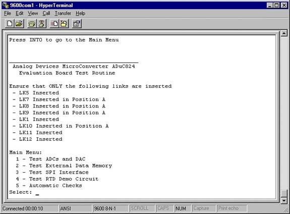
Open the preconfigured hyperterminal program 9600com1.ht (C:\ADuC\9600com1.ht). Slide LK3 to the OFF position and press the reset button. The line ‘Press INT0 to go to the Main Menu should appear’. Press INT0. The window should be updated as shown below.
Step 4:
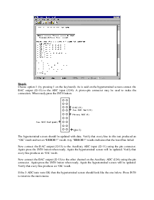
Choose option 1 (by pressing 1 on the keyboard). As is said on the hyperterminal screen connect the DAC output (J2-13) to the ADC input (J2-9). A pin-to-pin connector may be used to make the connection. When ready press the INT0 button.

! DAC (13)
! Aux ADC Ain3 (11)
! Primary ADC (9)
Aux ADC Ain5 (pin6) "
! (pin 1)
The hyperterminal screen should be updated with data. Verify that every line in this test produced an “OK” result and not an “ERROR!!” result. Any "ERROR!!" results indicates that the board has failed.
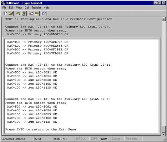
Now connect the DAC output (J2-13) to the Auxiliary ADC input (J2-11) using the pin connector. Again press the INT0 button when ready. Again the hyperterminal screen will be updated. Verify that every line produces an ‘OK’ result.
Now connect the DAC output (J2-13) to the other channel on the Auxiliary ADC (J2-6) using the pin connector. Again press the INT0 button when ready. Again the hyperterminal screen will be updated. Verify that every line produces an ‘OK’ result.
If the 3 ADC tests were OK then the hyperterminal screen should look like the one below. Press INT0 to return to the main menu.
Step 5:
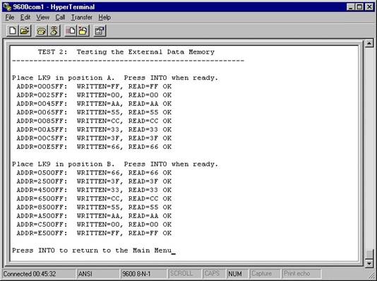
In the main menu choose Option 2 (press 2 on keyboard). Make sure that link 9 is in position A. If so press INT0 on the eval board. The hyperterminal screen should be updated with information. Verify that each of the lines ends with ‘OK’ and not ‘ERROR!’.
Now move LK9 into position B. Press INT0 on the evaluation board. The hyperterminal screen should again be updated with information. Verify that each of the lines ends with ‘OK’ and not ‘ERROR!’. If both tests passed then the hyperterminal screen should look like the following. Press INT0 to return to the main menu.
Step 6:
In the main menu choose Option 3 (press 3 on keyboard). Connect SCLOCK (J7-1) to P3.3 (J3-4) and press the INT0 button. Connect SDATA (J7-3) to P3.3 (J3-4). Press the INT0 button when ready. Connect SS (J7-7) to P3.3 (J3-4). Press the INT0 button when ready. If this test passed then the line “Testing SPI/I2C Interface... OK” should appear.
If the line “Testing SPI/I2C Interface... ERROR!” appears then an error has occurred and the board has failed.
Step 7:
In the main menu choose Option 4 (press 4 on keyboard). Reconfigure the following links:
LK5 – Slide to the OFF position
LK7 – Slide to Position B
LK8 – Slide to Position B
Remove any connector from Test 1 (step8) above.
When ready press INT0 and verify that the line says OK. Press INT0 to return to the main menu.
Step 8:
In the main menu choose Option 5 (press 5 on keyboard). This is an automatic test. Verify that the three lines say OK. Press INT0 to return to the main menu.
Note: The evaluation board passed the evaluation board test if the above routine (steps 8 " 12) can be successfully completed without any "ERROR!!" results.
Уважаемый посетитель!
Чтобы распечатать файл, скачайте его (в формате Word).
Ссылка на скачивание - внизу страницы.