Specification of some micromechanical gyro characteristics on basis of its design
 |
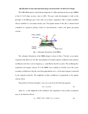
The schematic illustration of the MMG design is shown in Fig.1. The disc on an elastic suspension that allows for the disc three-degrees-of-freedom angular oscillations starts primary oscillations about the x axis at frequency ω, controlled by the drive system. The oscillating disc experiences the angular velocity W of the MMG base, resulting in Coriolis force that causes secondary oscillations of the disc about the perpendicular axis y of the same frequency measured by the capacitive pickoffs. The amplitude of these oscillations is proportional to the angular velocity W [1].
The position of the disc along the x axis, x(t), is given by the following equation:
![]() (1)
(1)
where X0 – is the amplitude of the oscillation. The magnitude of the Coriolis acceleration may be calculated as follows:
![]() (2)
(2)
MMG includes a resonant suspension – a proof mass (disc) hung on an elastic suspension. Resonant suspension is characterized by its resonant frequency and Q-factor. Resonant frequency is defined as follows:
 (3)
(3)
where K is stiffness of the suspension and J – moment of inertia of the disc. Resonant frequency and Q-factor may be defined by a method of generation of auto-oscillations. It is known that stable oscillations appear in a closed-loop system on the resonant frequency on following conditions:
1. Contour gain = 1;
2. Phase shift in open-loop system = 180°
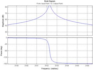
MMG is a high-Q resonant contour. Its bode diagram is shown in fig. 2. System of automatic adjustment of amplification is used to execute the first condition. A resonant element at the resonant frequency has a phase shift of 90°. Therefore a phase-shifting unit (in our case it is an integrator) must be added in series with resonant element in order to excite oscillations precisely at the resonant frequency. The Simulink-model of auto-oscillation generator is shown in fig. 3.
|
|
|
|
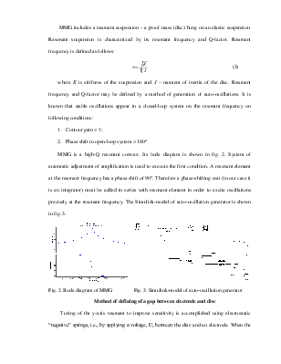
Fig. 2. Bode diagram of MMG |
Fig. 3. Simulink-model of auto-oscillation generator |
Method of defining of a gap between electrode and disc
Tuning of the y-axis resonant to improve sensitivity is accomplished using electrostatic “negative” springs, i.e., by applying a voltage, U, between the disc and an electrode. When the voltage is established between the moving disc and the electrode, the resulting attractive force reduces spring constant and thus adjusts the resonant frequency.
The spring force due to electrostatic forces is given by the following equations:
 (4)
(4)
where y is the gap between disc and electrode, ![]() is a permittivity, ε – inductivity (ε = 1 in vacuum), S – electrode area. The electromagnetic
spring constant, Kel, is given by:
is a permittivity, ε – inductivity (ε = 1 in vacuum), S – electrode area. The electromagnetic
spring constant, Kel, is given by:
 (5)
(5)
where С is a capacity of the gyroscopic sensor.
The y-axis resonant frequency, ω, is given by the following expression:
 (6)
(6)
where Kmech is the mechanical spring value and J is the moment of inertia of the disc [2]. A correction for “negative” spring must be considered while defining the resonant frequency of the oscillations around y-axis. The correction for the design of the MMG is about 1%. Since Kel has a negative value, so that as U increased, ω is decreased. Thereby, the desired mismatch of resonant frequencies may be approached by varying Kel.
Method of defining of a gap between electrode and disc is based on this fact. There is well-known expression defining y-axis resonant frequency:
 (7)
(7)
where K is the sum of the mechanical and “negative” spring. The gap y may be derived from equation (7) as shown in following equation:
Уважаемый посетитель!
Чтобы распечатать файл, скачайте его (в формате Word).
Ссылка на скачивание - внизу страницы.