QUADRATURE ERROR REDUCING CIRCUIT IN MICROMECHANICAL GYROSCOPE
Tatiana A. Andreeva
Central Research Institute “Elektropribor”, Malaya Posadskaya str. 30,
Saint-Petersburg, 197046, RUSSIA.
Tel: +7(812)4997809, E-mail: elprib@online.ru
Abstract – Quadrature error reducing circuit, which provides extraction proportional to the angular velocity useful signal from the output micromechanical gyroscope signal, is described in this paper. Simulation data and its experimental validation are also presented in this paper.
1. INTRODUCTION
The Central Research Institute “Elektropribor” started development of angular-rate-sensing Micromechanical Gyroscope (MMG) of 0.1-0.01 deg/s accuracy class in 2001 [1].
The MMG can be considered as a microelectromechanical system that consists of a micromechanical Silicon Module and microelectronic systems that actuate disc oscillations and detect its motion.
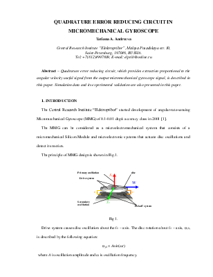
The principle of MMG design is shown in Fig.1.
 |
Fig 1.
Drive system causes disc oscillation about the f1 – axis. The disc rotation about f1 – axis, α f1, is described by the following equation:
α f1 = Asin(ωt)
where A is oscillation amplitude and ω is oscillation frequency.
The oscillating disc experiences angular velocity Ω of the MMG base, resulting in Coriolis force of the same frequency ω1 that causes secondary oscillations of the disc about the perpendicular axis:
α f2 ≈ 2ΩАωcos(ωt)
After simple transformation we obtain an expression:

where Av is the amplitude of these oscillations which is proportional to the angular velocity Ω.
2. QUADRATURE ERROR AND ITS CHARACTERISTICS
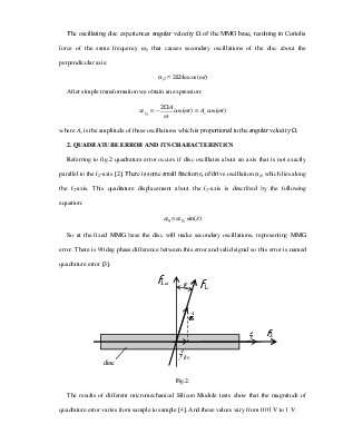
Referring to fig.2 quadrature error occurs if disc oscillates about an axis that is not exactly parallel to the f1-axis [2]. There is some small fraction ε, of drive oscillation α f1 which lies along the f2-axis. This quadrature displacement about the f2-axis is described by the following equation:
![]()
 So at the fixed MMG base
the disc will make secondary oscillations, representing MMG error. There is 90
deg phase difference between this error and valid signal so this error is named
quadrature error [3].
So at the fixed MMG base
the disc will make secondary oscillations, representing MMG error. There is 90
deg phase difference between this error and valid signal so this error is named
quadrature error [3].
Fig.2.
The results of different micromechanical Silicon Module tests show that the magnitude of quadrature error varies from sample to sample [4]. And these values vary from 0.01 V to 1 V.
The level of quadrature error exceeds the useful signal which is proportional to the angular velocity Ω [5].
3. QUADRATURE ERROR REDUCING CIRCUIT
So we have to provide detection of the valid signal on the background of quadrature error. There are lot’s of well-known methods for suppressing quadrature interference, but in view of design philosophy of our MMG all these methods can’t be used. That’s why we use an electronic block in the channel of output signal processing.
Consider the principle of the valid signal detection. Output voltage of “capacity-to-voltage” converter comes at the input of suggested scheme named Quadrature Error Reducing Circuit (QERC). Then the converted signal without quadrature error is demodulated and valid signal, proportional to measured angular velocity Ω, is detected. Immediate demodulation output voltage of the “capacity-to-voltage” converter (without offered scheme) is ineffective because there is a small phase shift, which causes a zero drift (MMG error).
The principle of QERC operation is compensating signal generation.
A simplified block diagram of this control system is shown in fig.3.
Fig.3.
The first input of this system is the signal determined by the following expression:
Uс-u = K·(Аqcos(ωt) + Аkvsin(ωt)),
where Аq is a quadrature error amplitude, Аkv is valid signal amplitude and Uс-u is an output signal from “capacity-to-voltage” converter, being the sum of valid signal and quadrature error.
The second input of the system is base voltage. The base voltage is a signal from drive, which is in-phase with quadrature component. Gained input signal arrives at the first multiplier where the quadrature component is demodulated. Then the constant signal, proportional to the amplitude of quadrature error, is extracted. This signal modulates the base voltage. In result we obtain a harmonic signal with the same amplitude and frequency as quadrature component. This signal is subtracted from the input signal and in the output of this block we have valid signal only. So the quadrature error is compensated.
4. TEST RESULTS
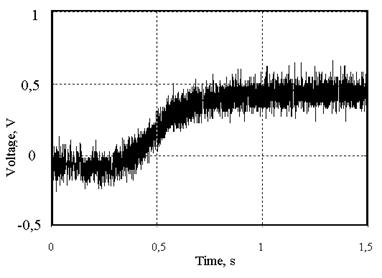
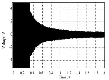
The simulation data are presented below. Transient function for different values of quadrature error (0.1, 0.2, 0.3 V) are presented in fig.4. In fig.5 an output signal from QERC is shown. We can see that at the first period from 0 to 0.5 s valid signal is not detected, because quadrature error has not compensated yet. But after 0.5 s we see only amplitude-modulated valid signal with envelope proportional to angular velocity Ω.
|
|
|
|
Fig.4 |
Fig.5 |
This scheme is realized as a printed board. Following experimental validation of the diagrams is presented below. Received diagrams are the same as simulation data. Output signal of QERC, presented in fig. 7 is received at the fixed MMG base.
|
|
|
|
Fig.6 |
Fig.7 |
This system compensates the quadrature error in any sample, therefore it is an adaptive system.
5. ACKNOWLEDGEMENTS
I would like to thank Iakov A. Nekrasov for his exemplary guidance, strong support and useful advices.
6. REFERENCES
1. Peshekhonov V.G. et al. The development of a micromechanical disc-shape gyroscope. //XII Saint Petersburg international conference on integrated navigation systems. - St.Petersburg: CSRI "Elektropribor", 2005. (In Russian)
2. Raspopov V.Ya. Micromechanical units. – Tula: Tula State University. 2004. (In Russian)
3. Ying W.Hsu. Method of canceling quadrature error in an angular rate sensor. Patent №: US 6,370,937, B2. - 2002.
4. Bagaeva S.V., Moiseev N.V. Test bench for micromechanical gyro dynamic characteristics examination. (In Russian)
5. Evstifeev M.I. Errors of the micromechanical gyro on a vibratory bed. // Gyroscopia and navigation. – 2002. – vol. 2. (In Russian)
Уважаемый посетитель!
Чтобы распечатать файл, скачайте его (в формате Word).
Ссылка на скачивание - внизу страницы.