


Annotation. 2
Contents. 3
Introduction. 4
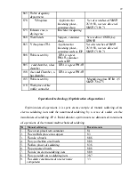
The description of the analogousand initial data. 5
Functional diagram.. 6
Actuator RD – 25FA.. 11
The block diagram.. 12
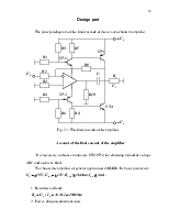
Design part 16
Development of technological process. 20
The economic substantiation. 26
Safety of habitability. 28
List of the literature. 32
The appendix. 33
Tens thousand various types of automatic control systems (ACS) are applied now in aircraft and an astronautics which provide high efficiency of productions.
Modern ACS represents the complicated dynamic systems ensuring high accuracy of improvement of control signals in conditions of action of various disturbing interferences. At large values of disturbances and levels of interferences normal operational conditions are upset, accuracy is reduced, and parameters of quality of transients in systems are worsened in comparison with the given specifications. Designing such ACS represents difficult enough problem as devices enter in them and objects of control of a various physical nature.
For obtaining proper characteristics ACS the designer should find conciliatory proposals, as requirements to accuracy and parameters of quality of transients mutually exclusive.
Stability is necessary, but an insufficient condition of normal functioning ACS. Presence of stability testifies only that the transient called by action of external effect or existence of nonzero entry conditions, is damping. But thus are not determined neither damp time, or maximum deflection of a controlled variable, number of oscillations. Namely these parameters also characterize regulation processes course quality.
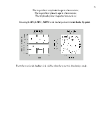
The large help in designing and analysis ACS to the engineer is given with software Simulink included in mathematical packet Mat Lab.
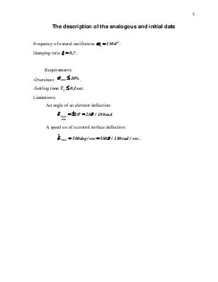
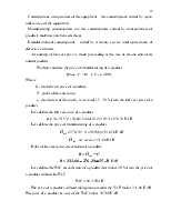
Frequency of
natural oscillations ![]()
Damping ratio ![]()
Requirements:
-Overshoot ![]() .
.
-Settling time
![]()
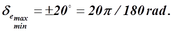
Limitations:
An angle of an elevator deflection:
A speed on of a control surface deflection:
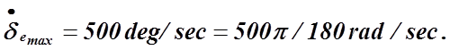
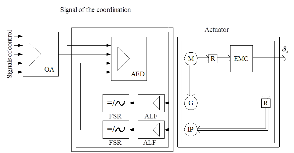
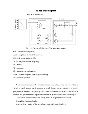
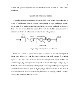
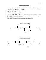
Fig. 1.1.Functional diagram of the servomechanism:
ОА – operational amplifier,
AED – amplifier of the electric drive,
M – motor,
G – generator,
IP – induction potentiometer,
EMC – electromagnetic coupling of coupling,
A servomechanism may be broadly defined as a closed-loop control system in which a small power input controls a much larger power output in a strictly proportionate manner. In applying such a mechanism to the automatic control of an aircraft, the system must be capable of continuous operation and have the ability to
1) detect the difference between an input and an output (error detection);
2) amplify the error signals;
3) control the closing of the servo loop by providing the feedback.
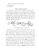
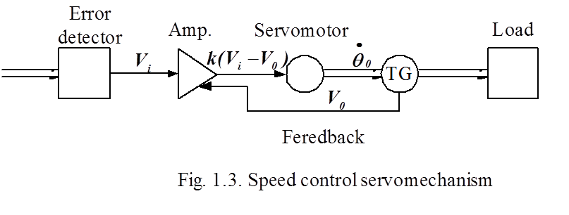
There are two main classes of servomechanisms:
1) position control,
2) speed control.
A block diagram of a
position control servomechanism is illustrated in Fig. 1.2, and from this it
will be noted that it is one in which a load has to be rotated through an
output angle ![]() corresponding to an input angle
corresponding to an input angle ![]() of a controlling shaft. The
controlling shaft is, in this example, mechanically coupled to the wiper arm of
a potentiometer, the signal output of which is fed to a servomotor via an
amplifier. The output angle of the load is measured by the second
potentiometer whose wiper arm is mechanically coupled to an output shaft.
of a controlling shaft. The
controlling shaft is, in this example, mechanically coupled to the wiper arm of
a potentiometer, the signal output of which is fed to a servomotor via an
amplifier. The output angle of the load is measured by the second
potentiometer whose wiper arm is mechanically coupled to an output shaft.
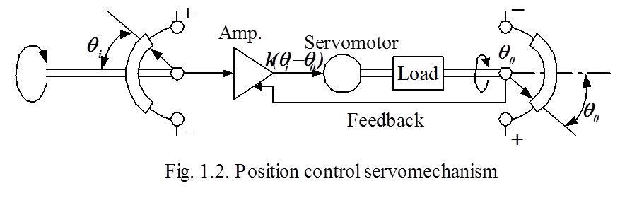
The potentiometers are electrically
connected such that when their wiper arms occupy corresponding angular
positions the servomechanism is in a “null” or zero signal condition. When it
is required to move the load to a particular angular position ![]() the controlling shaft is rotated
through the appropriate number of degrees; thus the mechanism is no longer at a
“null” and an error signal corresponding to angle
the controlling shaft is rotated
through the appropriate number of degrees; thus the mechanism is no longer at a
“null” and an error signal corresponding to angle ![]() is
produced and fed to the amplifier. The amplifier has an amplification factor of
is
produced and fed to the amplifier. The amplifier has an amplification factor of
![]() , and therefore the input to the
servomotor is increased to
, and therefore the input to the
servomotor is increased to ![]() . As the motor
positions the load, the output shaft rotates the wiper arm of the second
potentiometer to produce a signal corresponding to an angle
. As the motor
positions the load, the output shaft rotates the wiper arm of the second
potentiometer to produce a signal corresponding to an angle ![]() . This signal is fed back to the
amplifier thereby reducing the input error signal to the amplifier so that the
real output from this unit to the servomotor is
. This signal is fed back to the
amplifier thereby reducing the input error signal to the amplifier so that the
real output from this unit to the servomotor is ![]() .
When the load finally reaches the position required, the servomechanism will
then be at a new “null” condition.
.
When the load finally reaches the position required, the servomechanism will
then be at a new “null” condition.
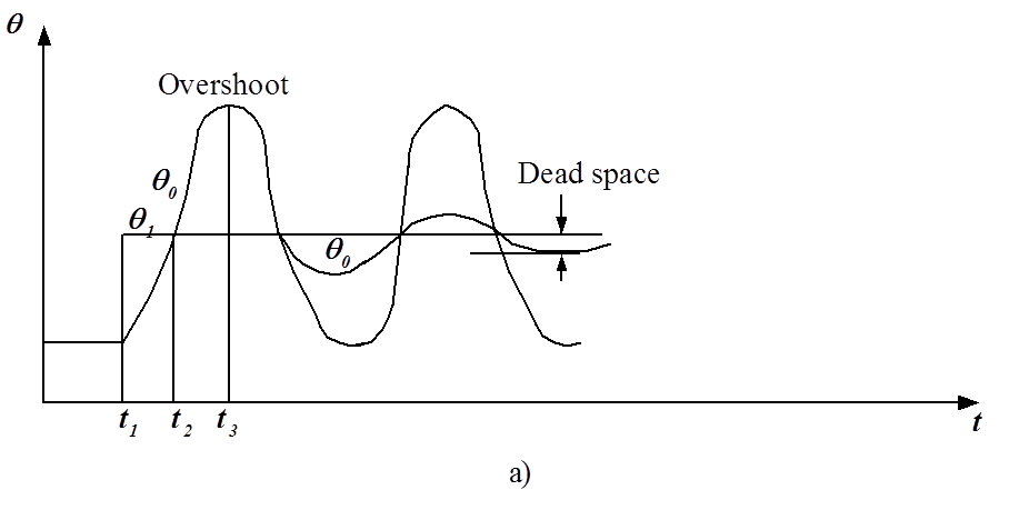
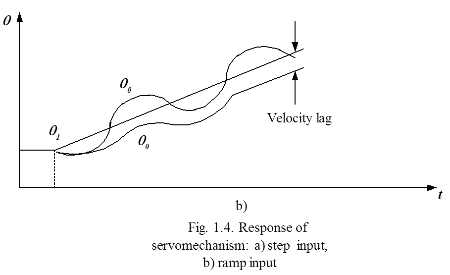
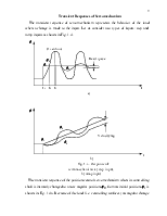
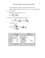
The transient response of the position control servomechanism when its
controlling shaft is instantly changed to a new angular position ![]() from an initial position
from an initial position ![]() is shown in Fig. 1.4a. Because of
the load (i.e. controlling surfaces) an angular change at the servomechanism
output will not be able to follow exactly that at the input, with the result
that a large error signal is produced initially. This causes the load to be
accelerated to its required position
is shown in Fig. 1.4a. Because of
the load (i.e. controlling surfaces) an angular change at the servomechanism
output will not be able to follow exactly that at the input, with the result
that a large error signal is produced initially. This causes the load to be
accelerated to its required position ![]() , and thereby
reduces the error to zero (instant
, and thereby
reduces the error to zero (instant ![]() ). At this point
however, and although the acceleration is zero, the control surfaces have
reached a steady rate of change, and so it overshoots resulting in an increase
of error in the opposite sense to decelerate the load until it comes to rest in
the opposite direction (instant
). At this point
however, and although the acceleration is zero, the control surfaces have
reached a steady rate of change, and so it overshoots resulting in an increase
of error in the opposite sense to decelerate the load until it comes to rest in
the opposite direction (instant ![]() ). By this time
the error signal is equal to the original error signal but of opposite
polarity, and so the load is accelerated back towards the required position and
produces another overshoot, and so on. If the frictional losses in the system
are negligible, a continuous oscillation is produced.
). By this time
the error signal is equal to the original error signal but of opposite
polarity, and so the load is accelerated back towards the required position and
produces another overshoot, and so on. If the frictional losses in the system
are negligible, a continuous oscillation is produced.
Уважаемый посетитель!
Чтобы распечатать файл, скачайте его (в формате Word).
Ссылка на скачивание - внизу страницы.